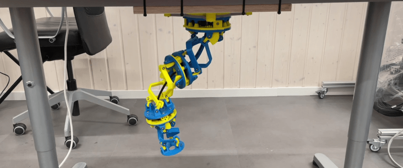
Hinge joints are usually the simplest to use for robotic applications, but if you want motion that looks more organic, rolling joint (or rolling contact) mechanisms are worth a look. [Skyentific] is experimenting with this mechanism and built a 6-degree-of-freedom robotic arm with it.
The mechanism doesn’t necessarily need the physical surfaces to roll across each other to work, and you can get to two degrees of freedom with the virtual rolling sphere mechanism. [Skyentific] demonstrates how these work with both cardboard cutouts and 3D printed models. Stacking three of these mechanisms on top of each other, with each stage driven by three Dynamixel servos, the motion seems almost serpentine.
Since the servos are driving the small bottom linkages of each stage, they are operating at a significant mechanical disadvantage. The arm can just barely keep itself upright on top of the table, so [Skyentific] mounted it upside down to the bottom of the table to reduce the load of its weight. With the front stage removed, the load is significantly reduced, and it doesn’t struggle as much.
An interesting advantage of this mechanism is that there is always a straight path down the center for cabling. The length of this line between the two plates remains the same throughout the entire range of motion, so it can also be used to route a rigid drive shaft. This is actually what was done on the LIMS2-AMBIDEX robot to rotate its hand, and is also where saw this mechanism for the first time. Interestingly, that implementation didn’t drive the linkages themselves, but used tension cables around the mechanism. We also see this in a very similar tentacle robot, so it might be a better option.


This robot arm is really cool, and as a yt comment said, “aesthetic”, but I do think using 9 servos for 6 DoF isn’t the best idea. Wouldn’t lack of precision in the servo command make them sometimes work against each other ?
Also, with linkages like this, it was bound to be springy. Maybe some ribs should be added in some places, however he didn’t do it probably to minimize collisions.
He mentioned in the video that having the servos work against each other is a useful feature because it allows him to pretension the servo gears against backlash.
Wondering if you could get the later stages controlled with bowden cables which might enable some creative rotations as well
Aaaannd one of the links show something similar (facepalm)
It looks like some of the servos lift more weight than others when it’s tilted over. I wonder if that could be corrected in software, make the other servos move farther when it’s lopsided.
Very cool but it’s also wobbly which radically reduces the number of applications it can be used for.
It makes sense to have the tension cables on the outside if you have a rigid structure down the middle. That way you can use the rigid structure as a lever, allowing you to use a weaker motor for the tension cables
“Pros: -It is cool”
This factor should never be underestimated :)
Needs a knife mounted on the end.