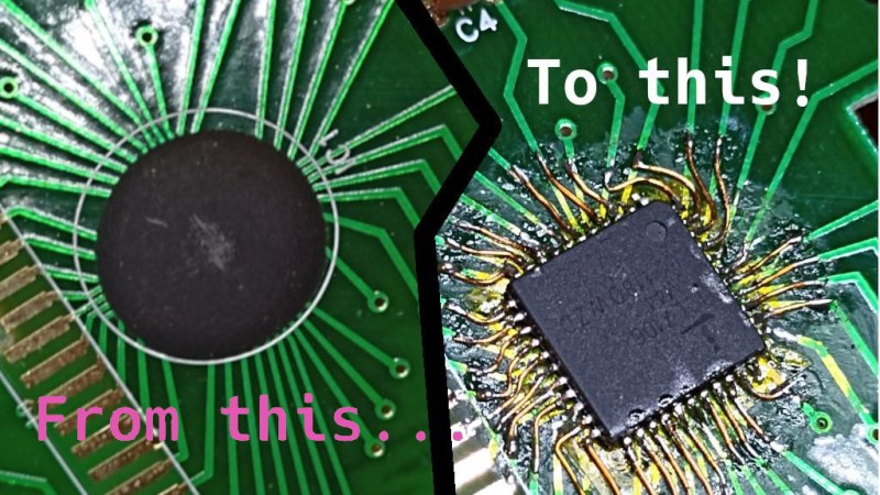
The black blobs on cheap PCBs haunt those of us with a habit of taking things apart when they fail. There’s no part number to look up, no pinout to probe, and if magic smoke is released from the epoxy-buried silicon, the entire PCB is toast. That’s why it matters that [Throbscottle] shared his journey of repairing a vintage multimeter whose epoxy-covered single-chip-multimeter ICL7106 heart developed an internal reference fault. When a multimeter’s internal voltage reference goes, the meter naturally becomes useless. Cheaper multimeters, we bin, but this one arguably was worth reviving.
[Throbscottle] doesn’t just show what he accomplished, he also demonstrates exactly how he went through the process, in a way that we can learn to repeat it if ever needed. Instructions on removing the epoxy coating, isolating IC pins from shorting to newly uncovered tracks, matching pinouts between the COB (Chip On Board, the epoxy-covered silicon) and the QFP packages, carefully attaching wires to the board from the QFP’s legs, then checking the connections – he went out of his way to make the trick of this repair accessible to us. The Instructables UI doesn’t make it obvious, but there’s a large number of high-quality pictures for each step, too.
The multimeter measures once again and is back in [Throbscottle]’s arsenal. He’s got a prolific history of sharing his methods with hackers – as far back as 2011, we’ve covered his guide on reverse-engineering PCBs, a skillset that no doubt made this repair possible. This hack, in turn proves to us that, even when facing the void of an epoxy blob, we have a shot at repairing the thing. If you wonder why these black blobs plague all the cheap devices, here’s an intro.
We thank [electronoob] for sharing this with us!


Why is a cheap multimeter made in this century “vintage”?
Seems to be an editor error as the page labels it as “of early 2000’s vintage” which is proper use of the term.
not an editor error – I saw ‘vintage’ and glossed over the ‘2000’ part when writing the post! my bad!
Heroic!
Yep, been there. ‘Heroic effort’ was what I thought, too.
I’m sure that 99% of the connections drive the LCD, so it shouldn’t be too hard to debug, … but still?
I like the combination of digital and analogue meters in one package!
Missed opportunity to point out the irony of epoxy now being a good idea to make sure that new chip stays put
that’s what we have you all for ^__^
Proper hack! Only downside is it’s way beyond my meager capabilities, but that’s only my own fault.
If it must be stuck down, to avoid dislodging it, I vote for using clear enamel, rather than apoxy, show off the work and make the chip details visible for any potential future hacker to see.
I don’t know if it’s important in this case, but as a general rule sensitive analog semiconductors should not be allowed to be exposed to even low levels of light unless their purpose is to detect light. Light + semiconductor junction –> current.
It is not important in this case. What was originally under the dark blob was most likely a raw silicon chip, which would need to be protected. What it was replaced with, however, was an integrated circuit. The raw silicon chip of an integrated circuit is first connected to the solderable pinouts and then the package is encased in typically black plastic epoxy or thermoset, leaving only the solderable pinouts exposed. Bottom line is the silicon is already protected, securing it with clear enamel or epoxy would be primarily to show off the soldering work and perhaps the part number.
But the insides of gadgets are usually dark….
That’s probably the best Instructable I’ve seen. Well explained, good photos and drawings, magnet wire + polyamide tape. Nice.
Nice
The blob type designs are usually the cheap ones, so I wonder if it’s worth the effort.
Nicely done nevertheless.