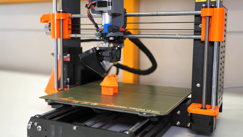
It always seemed to us that the Z-axis on a 3D printer, or pretty much any CNC machine for that matter, is criminally underused. To have the X- and Y-axes working together to make smooth planar motions while the Z-axis just sits there waiting for its big moment, which ends up just moving the print head and the bed another fraction of a millimeter from each other just doesn’t seem fair. Can’t the Z-axis have a little more fun?
Of course it can, and while non-planar 3D printing is nothing new, [Stefan] over at CNC Kitchen shows us a literal twist on the concept with this four-axis non-planar printer. For obvious reasons, it’s called the “RotBot,” and it comes via the Zurich University of Applied Sciences, where [Michael Wüthrich] and colleagues have been experimenting with different slicing strategies to make overhang printing more manageable. The hardware side of things is actually pretty intuitive, especially if you’ve ever seen an industrial waterjet cutter in action. They modified a Prusa printer by adding a rotating extension to the print head, putting the nozzle at a 45° angle to the print bed. A slip ring connects the heater and fan and allows the head to rotate 360°, with the extruder living above the swiveling head.
On the software side, the Zurich team came up with some clever workarounds to make conical slicing work using off-the-shelf slicers. As [Stefan] explains, the team used a “pre-deformation” step to warp the model and trick the slicer into generating the conical G-code. The G-code is then back-transformed in exactly the opposite process as pre-deformation before being fed to the printer. The transformation steps are done with a bit of Python code, and the results are pretty neat. Watching the four axes all work together simultaneously is quite satisfying, as are the huge overhangs with no visible means of support.
The academic paper on this is probably worth a read, and thankfully, the code for everything is all open-sourced. We’re interested to see if this catches on with the community.


A extra… oh man…
Brilynt cmmnt, Jan.
Nott hrd ta rede et al.
Try speaking German, if it’s a foreign language to you. Then we can mock you.
Overhangs are cool… but show me a closeup of a benchy print!
To overcome the limitation of having the rotational axis, they need to add a fifth axis to adjust the print angle. Figuring out the optimal print angle will be another problem to solve.
>> ‘Figuring (that out) will be another problem to solve’
You… say that like it’s a bad thing….
CNC mills love and utilize the Z-axis.
Next up, not only rotating the print head at a fixed angle, but also being able to change that angle.
Essentially, we need a prnt head attached to a robot arm, with it’s waist attached to an x,y,z grantee, such that it can also rotate around the grantee mounts. Then you can literally print any non superimposed shape.
I’m always worried about which of these new 3D printing techniques is secretly a patent minefield. I feel like there’s some patent problem with at least one non-planar printing techniques, but I don’t remember what/which and I sure am not going to go look it up.
.. I’m not sure if there is a patent for a machine using an X, Y, Z, and A axis.
Regarding the comment about finding the optimum print angle, it’s not difficult to determine the vector that is normal to each triangle in a mesh. If we have vertices A, B and C we calculate the vectors that point from B to A and C to A. Their cross product is parallel to the surface normal of the triangle. That could be used to set the angle of the print head. Tricky things like how to handle abrupt changes of the surface normal might be addressed by adding fillets to smooth out transitions like that.
This calculation is most commonly used when rendering mesh-based models so there should be plenty of code examples out there to take a look at.
Hmmm. Wonder if the software can be used at a shallower angle with a non-modified Cartesian printer.
For optimum angle, you could use a straight skeleton algorithm in three dimensions, to determine the angle of each face, and build it out from the center.
Good afternoon all,
This is a phenomenal breakthrough, I have been looking in to all the files including the script files in Python, excellent work, nevertheless one thing is missing is all that, the marlin configuration and modification files, also how and where connect the Z-Rotation motor to, it would be nice to have some complete concise Opensource compilation of all this so that amateurs like me can make one and be part of the testing bodies. Thanks guys