We’ve seen plenty of people 3D printing custom gears over the years, but [Mr Innovative] decided against an additive process for his bespoke component. He ended up using a simple CNC machine that makes use of several components that were either salvaged from a 3D printer or produced on one. Using a small saw blade, the machine cuts gear teeth into some plastic material and — presumably — could cut gears into anything the saw blade was able to slice into, especially if you added a little lubrication, cooling, and dust removal.
If you’ve built a 3D printer, you’ll see a lot of familiar parts. Stepper motors, aluminum extrusion, straight rods, bearing blocks, and rod holders are all used in the build. There’s also a lead screw and the associated components you usually see in a printer’s Z-axis. Naturally, an Arduino drives the whole affair.
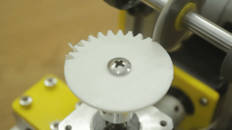
The saw blade was custom-made from a washer, grinding an edge and using a 3D printed template to cut teeth in it. We might have been more inclined to use a cut-off wheel from a rotary tool, but this certainly did the trick. An LCD accepts the gear diameter and number of teeth. The stepper rotates the correct number of degrees and another stepper lowers the cutting head which is spinning with a common DC motor.
As impressive as this machine is, the fact remains that a 3D printer can produce more complex designs. For example, a herringbone pattern can help with alignment issues. It has been done many times. You can even use a resin printer, although you might prefer to stick with FDM.


That’s interesting but those aren’t involute shaped gear teeth, so they won’t properly mesh with anything. While it’s possible to make a form cutter to approximate involute teeth, those are typically only good for a small range of gear teeth of a particular pitch.
If he had coordinated a slide for the cutter he could have generated usable gear teeth with a flat-sided tapered cutter. So, maybe the 2.0 version?
“We might have been more inclined to use a cut-off wheel from a rotary tool,”
Adding to three_d_dave’s comment, you need to be able to cut with the appropriate tooth profile. While I’m sure it’s possible to make your own gear cutter with the correct profile, and I know this isn’t BuyADay.com, but there is a set on amazon for ~$20. Bonus if your gear cutter machine takes standard gear cutter tools making it easier to cut different gears.
FDM 3D printed gears are ok if the gears are big enough, but for smaller gears the resolution isn’t really there. Great to see a solution which could allow making smaller gears at home.
I think I’d just use a regular slitting saw and turn this method into a CNC algorithm:
https://www.youtube.com/watch?v=eC-OctJoWv4
Thank you for (again) dropping a link to AndysMachines. I thought he was already mentioned on Hackaday, bt I could not find the reference.
Andy knows what he’s doing, and also makes very nice explanatory video’s.
It’s very much the opposite here. The youtuber who made this video is just fooling a bit around, and probably cares more about youtube likes then either building or teaching something that works properly. Using a convex mill to cut concave tooth would be the very least improvement to approximate something useful
Great video. Although this is limited to larger gear sizes due to the blade thickness, but still a great option if you are caught without the right cutting tool. However it does feel like a lot of work, 160 cuts, plus (at least) 24 passes with a ball end mill bit, for only 12 teeth. Buying a gear cutter still looks like a good option.
You just need a sawblade that is thin enough for the smallest gear you’re going to make. The rest is software.
@rewolff
But there is a limit to how thin the saw blade can be and still be rigged enough to cut accurately. This limits the size of the teeth that can be cut with this method.
The cut-off blade is using the concept that the pressure angle at the base circle is 90 degrees. A typical gear hob uses essentially truncated triangular teeth to mimic the mating rack that are set to cut at the pressure angle of the pitch circle and is much more efficient. Form tool gear cutters are only good for a small range of teeth, while a gear hob is limited by the size of the truncation – one could fairly easily make a gear hob for small teeth getting cut in soft materials. Maybe Old Tony could give it a shot?
Awesome video. And yeah, that’s exactly how you’d do it with a thinner cutoff wheel.
I love it when he chucks the sharpie on the mill to CNC mark the blank. Horrible runout, though. He needs a precision Sharpie.
Although he lost me when he required me to have a rotary index chuck. Sigh. Add it to the shopping list.
Came in to say this. It looks like the cutter itself may be the correct shape for a proper involute but, our course, the tooth forms cut BY it are not correct. You need to use that cutter to make an intermediate cutter then use that to cut the teeth. Unless you don’t care about longevity, friction or even proper meshing and function.
I see Andy’s slitting saw method is here. I also developed a method that works like a shaper but uses an end mill or d-bit cutter with straight flanks: https://youtu.be/8muPReyGR6s It works for helical and harringbone gears. I’ve not yet tried bevel gears but with the right setup you could also do them.
Is there a link for this project files and arduino code?
please make a clock (using gears)
If you had a thin enough flat cutting saw blade you could move in towards and away from the gear axis, perhaps with some sideways motions too, while rotating the gear on axis, and thereby trace out a proper involute curve. The sort of cutting shown in the vid, where the cross-section of the cutting blade gives the shape of the tooth isn’t going to do proepr involutes, but proper involutes could be done with minimal hardware modifications and only a little work in improving the software. You can find code online which will generate appropriate involute curves for a given gear size and tooth count, the cutter shown here could have these pieces of code implanted in to its firmware.
Check out how to hob gears. Basically you use a straight toothed (easy to make) cutter and cut it as the gear rotates. It makes an involute. Easier to understand when you see it. It has been done for centuries.
Here is one way to hob at home.
https://youtu.be/ZhICrb0Tbn4
(serves as a reminder how much video camera quality has improved in the last several years)
With a few modifications, I could see this cutting and polishing a lens in acrylic (or resin).
Turntable holds lens, replace grinder with buffing pad.
There are a couple of YT videos about these little machines, one that has more plastic in the construction yet cuts better gears.
A decent approximation of involute gear teeth can be done with a multi tooth cutter with straight sides. The first cut carves a straight sided slot in the center, while the two cutters to either side cut those teeth partially at a different angle due to the rotation. Rotate one tooth and cut again. Each tooth gets three facets at different angles and the gear being cut only has to make one full revolution.
This process is best for gears that can be run together for a while at looser mesh with lapping compound to round off the edges between facets, then cleaned off and installed at correct running mesh with lube.
It’s not a proper gear tooth. The full gear is never shown, so I suspect the last tooth doesn’t line up with the first. If it can only cut trough 3D-printed plastic disks, why not just 3D print the actual gear profile as well?
With FDM 3D printers there a limit to the amount of detail you can get and hence teeth size. While I’ve successfully printed may gears, I’m unable to print smaller gears, like those found in 40mm hobby servo for example.