One generally reads a data sheet in one of two ways. The first is to take every spec at face value, figuring that the engineers have taken everything into account and presented each number as the absolute limit that will prevent the Magic Smoke from escaping. The other way is to throw out the data sheet and just try whatever you want, figuring that the engineers played it as safely as possible.
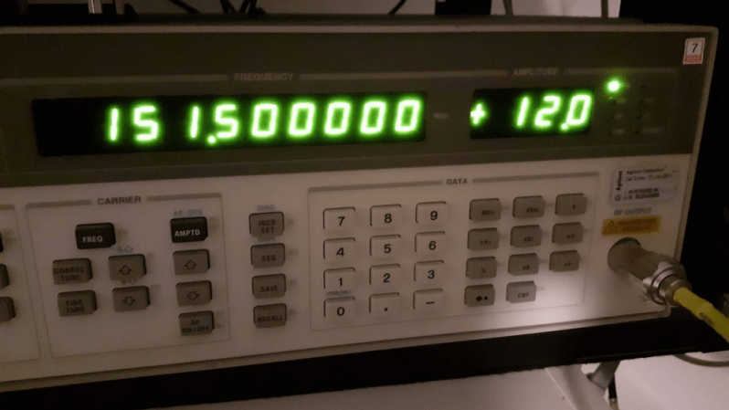
The latter case seems to have been the motivation behind pushing an ATtiny way, WAY beyond what the spec sheet says is possible. According to [SM6VFZ], the specs on the ATtiny817 show that the 12-bit timer/counter D (TCD) should be limited to a measly 32 MHz maximum frequency, above which one is supposed to employ the counter’s internal prescaler. But by using a 10-MHz precision frequency generator as an external clock, [SM6VFZ] found that inputs up to slightly above 151 MHz were countable with 1-Hz precision. Above that point, things started to drift, but that’s still pretty great performance from something cobbled together on an eval board in a decidedly suboptimal way.
We’d imagine this result could lead to some interesting projects, since the undocumented limit for this timer puts it well within range of multiple amateur radio allocations. Even if it doesn’t prove useful, that’s OK — just seeing how far things can be pushed is cool too. And it’s not like this is the first time we’ve caught [SM6VFZ] persuading an ATtiny to do unusual things, either.


Damn, if he can tease that up to 158.7MHz with some fine-tuning of the circuit, there’s pretty much a 2m-band LO oscillator right there.
Pretty sure my FT-857D drifts more than 1Hz at those frequencies.
Hmmm, or read the damn article better… it’d make a frequency read-out, not a LO. Still, damn impressive.
TCD is a (crude) waveform generator with two bits output and an internal counter. You can use it in counter mode, or in divide-by-n mode with the two output bits turned on/off at arbitrary points in the cycle. Assuming the output pins can also go to 150 MHz, you could do CW (and maybe AM?), but it would be at an even division of the reference. So if the reference was 150 MHz you’d be stuck with 150 MHz, 75, 50, 37.5, 30, etc. At 1 MHz your synthesizable freqs would be 142 KHz apart. I imagine you’d have to go a lot lower than that before you could do decent FM or PM.
Argh.. the frequence resolution would be 142 KHz at *5* MHz. At 1 MHz they would be 6.6 KHz apart.
Years ago, I got a few such AVRs’ timers up to 128MHz for simulating FPD-Link for driving old lvds laptop LCDs via the PWM/dead-timers. (128Mbps, not exactly 60Hz refresh, heh!).
To be honest, I thought it a bit of a fluke that it worked at such speeds. Great to see someone else accomplish similar, finally!
Yeah, some of the ATtiny (261/461/861 IIRC, probably more) have an internal PLL that can go up to 64MHz and drive the PWM with it. What a sweet spot for functionality and ease of development these chips have been.
That sounds a bit interesting, did you blog it anywhere?
Thanks for asking… There’s a *really* simplistic use of it at https://hackaday.io/project/3898-avr-lvds-lcd-binary-clock
but links from there point to more sophisticated implementations, vids, docs, and code.
The key factors are the PLL and using dead-timers, which allows for shifting the various PWM outputs relative to each other.
@Macegr is spot-on about the faster timer-counter opening doors. The Tiny861 and the Tiny85 became my go-tos, but I started with the AT90PWM series.
This frequency counter is especially interesting to me, since I hadn’t thought of using the high speed timer-counters the other way-round. To measure. More doors open. And also, as I said before, I was rather surprised with getting such high speeds out of it, and hadn’t previously heard of anyone else getting similar results. In the interest of the scientific method, this is great news! Hypothesis Confirmed by a peer’s loosely-related experiment.
Impressive, it is indeed. However it is not ‘incredible’ : I believe it may ne useful to remind that the specification is a commitment from the manufacturer that 99.99% of the chips will be able to deliver the written performance within the full temperature / operating voltage / input voltage / … range.
It is no surprise that a given chip, in a specific operating condition can achieve better than that. But you can not be sure and real testing becomes necessary.
Why not use something like MC12080 instead? Just add a buffer/amplifier on the input and achieve much higher frequency range?
Because the MC12080 is not a counter? (it’s just a prescaler)
Because the MC12080 is five times the cost of an ATTiny817 (and still requires a separate counter, say an ATTiny817)?
Because using a chip for its intended purpose isn’t a hack?
You use a frequency divider to extend the range of the timer/counter module of the uC, instead of exceeding SOAR of the part. The point of datasheet specification is that it covers worst case scenarios, for a reason – they happen. There is a bit of wiggle room, 10-20% maybe, but not over 460%!
So the poor attiny got overclocked, and it works for one person. Doesn’t mean it will work for anybody else. Or it will work for some people, but not for others. And we don’t know the long-term reliability. What if after ~100 hours of abuse it starts to miscount the cycles? What if after ~150 hours timer/counter burns out? Datasheet specification assumes at least 10 years of constant operation, usually 25 years or more.
And I work on a project where part gets overclocked by fairly tame (in comparison) 20%…
Fifty years ago, frequency counters for hobbyists were TTL and needed a prescaler to go above about 20MHz. They were ecl, and got hot. The early ones only worked to about 150MHz. But they were decade counters, making it easy to extend frequency counters.
It got better later, frequency counters pushed higher in frequency. And faster prescalers.
But they seem to have faded, the decade ones. Other schemes avoid them. But lots of prescalers with binary count.
In the interest of creating a product, you’re spot-on. You also forgot to mention other factors like temperature, which could make for the same machine’s working great in a workshop, but failing in the field.
This would be questionable engineering.
But, engineering blogs are not at all hard to find; it seems you’re missing the point clearly stated in this site’s domain name.
As far as “it works for one person…” I think I can safely vouch that the key-factor has been shown to work for me, as well… That makes two!
That doesn’t mean it should be considered reliable, but sharing these sorts of results does open doors for experimentation or quick one-off test-jigs, or even art, which is kinda what this site is about. “hack” ~= “YMMV”… Do we need to keep reminding folk of that?
It’s one of those cases where going for a commercial ‘off-the-shelf’ solution is just easier and cheaper than doing it yourself.
There’s plenty of ‘events’ companies (my brother works for one) who spend all their time either setting up festivals/gigs/rallies/tradeshows etc. or taking them down again. They also have all the specialised equipment (like portaloos!) which you’re unlikely to have lying around and would be difficult to build and maintain.
https://opautoclicker.dev/
When you go beyond specs you are just playing the silicon lottery.
I could be wrong, but it looks like in this example the chip still works within the spec.
In the datasheet there is actually description of a case where external clock for this particular counter (TDC) is 10 MHz.
32 kHz is by far not the top limit.
Still, it’s an interesting project, it made me order some ATTINY817’s
It would be interesting to see how hot the chip gets, driving 150MHz into it like that. Maybe compare one fed 30MHz to one fed 150, and measure the temperature rise after a minute or ten. Although it’d only be the first couple of LSBs that’d be seriously over clocked, so maybe not enough actual dissipation to drive the package temp up noticably. Might be a hot spot on the die though. Seems like something that might just fail after some longer interval, maybe an hour, maybe 100 hours, who knows.
why would feeding the external clkpin 150MHz make it hot. it’s only to increment a counter and then accumulate the result it is not doing anything special at all. the 10mhz on the external osc clock specifies 8Mhz max so I don’t think that would matter a lot either.
Just add a proper prescaler and be done with it. Analog Devices Inc. (ADI) bought out a bunch of RF chip manufacturers. Look here:
https://www.analog.com/en/parametricsearch/10720#/