PCB inductors are a subject that has appeared here at Hackaday many times, perhaps most notably in the electromagnetic exploits of [Carl Bugeja]. But there is still much to be learned in the creation of the inductors themselves, and [atomic14] has recently been investigating their automatic creation through scripting.
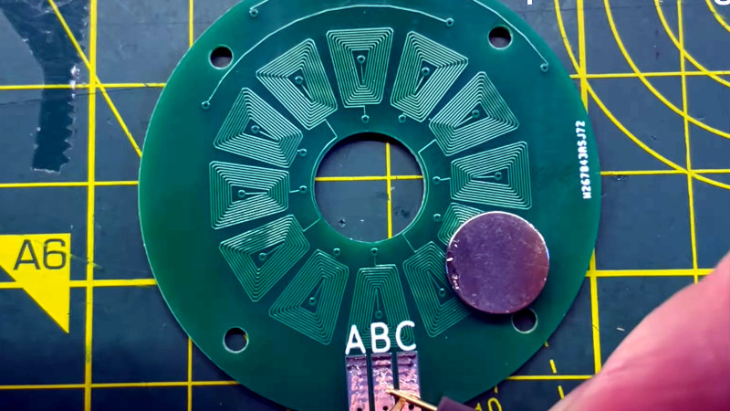
A simple spiral trace is easy enough to create, but when for example creating a circular array of coils for an electric motor there’s a need for more complex shapes. Drawing a trapezoidal spiral is a surprisingly difficult task for a script, and we’re treated to a variety of algorithms in the path to achieving a usable design.
Having perfected the algorithm, how to bring it into KiCAD? The PCB CAD package has its own Python environment built-in, but it’s not the most flexible in which to develop. The solution is to write a simple JSON interpreter in KiCAD, and leave the spiral generation to an external script that passes a JSON. This also leaves the possibility of using the same code in other PCB packages.
You can watch the whole video below the break. Meanwhile for more PCB electromagnetics, watch [Carl Bugeja]’s 2019 Supercon interview.


What a wonderful and helpful script!
In some cases, setting the KiCad interactive router to walk around mode can make a quick work of spirals. Once the outermost loop is in place, the rest will nicely follow it at the minimum spacing.
Great comment, thanks for the tip
I was thinking OpenSCAD=> SVG=> KiCAD PCB
But I suppose I’m just defaulting to the tools I know best.
Man, using openSCAD for PCB design sounds pretty intense. I’m glad someone’s doing it, and even more glad it’s not me!
I just realized, after reading the other reply, that Twisty is saying he’d use OpenSCAD to define the geometry and then export it to KiCAD (I thought they were saying they would rather use OpenSCAD for PCB design than KiCAD).
While OpenSCAD is a usable language, it’s not great, and KiCAD already has great python integration. Using OpenSCAD would essentially be using a worse language through a manual import process to achieve the same goal.
Same, I would usually just do this in Solidworks or Fusion and export the lines. There is something to be said for just sucking it up and making the tool to do this from the primary software natively.
As a professional SW user, it’s very much not what I’d recommend to define any kind of profile such as this. You’d have to be pretty familiar with the program to not fall into sketch overconstraint conditions, and designing it in a robust way would require a long feature tree of sketches with each representing duplicated work from the previous ring. Having easily-changed parameters would also require a lot of thought, and number of rings would require more of the previously-mentioned duplication of work, it simply couldn’t be done parametrically outside of writing a plugin (and at that point you’re just doing the same thing you’d be doing in KiCad, just through a more obtuse API).
This is a task that begs to be done via script, and KiCad’s python integration is extremely easy to use.
The script looks like it needs some work. Note the non-uniform spacing coil to coil. Time for a pull request.
Is that due to the direction of coil rotation alternating? I think the centre vias of each coil are probably correctly placed, but where a counterclockwise spiral is placed next to a clockwise one (or vice versa) the outermost tracks are immediately adjacent (or apart), resulting in an uneven gap between the coils.
Good catch! Accounting for that would be as good an improvement as any, though.
I did this back in 2009, using a python script that injected console commands into Eagle. The stator itself was for an in-hub drive motor for a solar powered race car. It was a 40 pole 4 turn design, with the traces barrel shifting on every pole in order to minimize eddy currents. The PCB stack called for 26 layers of 8oz copper, with about 90% fill, and a ton of laser drilled buried vias. The fab was excited for the challenge; they had to peck drill for the first time, and it ended up damaging several conveyor belts.