Scripting Coils For PCB Motors

PCB inductors are a subject that has appeared here at Hackaday many times, perhaps most notably in the electromagnetic exploits of [Carl Bugeja]. But there is still much to be learned in the creation of the inductors themselves, and [atomic14] has recently been investigating their automatic creation through scripting.

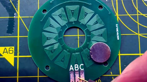
A simple spiral trace is easy enough to create, but when for example creating a circular array of coils for an electric motor there’s a need for more complex shapes. Drawing a trapezoidal spiral is a surprisingly difficult task for a script, and we’re treated to a variety of algorithms in the path to achieving a usable design.

Having perfected the algorithm, how to bring it into KiCAD?  The PCB CAD package has its own Python environment built-in, but it’s not the most flexible in which to develop. The solution is to write a simple JSON interpreter in KiCAD, and leave the spiral generation to an external script that passes a JSON. This also leaves the possibility of using the same code in other PCB packages.

You can watch the whole video below the break. Meanwhile for more PCB electromagnetics, watch [Carl Bugeja]’s 2019 Supercon interview.

Continue reading “Scripting Coils For PCB Motors”

A Fast Linear Actuator Entirely In One PCB

There are many ways to make a linear actuator, a device for moving something is a straight line. Most of the easier to make ones use a conventional motor and a mechanical linkage such as a rack and pinion or a lead screw, but [Ben Wang] has gone for something far more elegant. His linear actuator uses a linear motor, a linear array of coils for the motor phases, working against a line of magnets. Even better than that, he’s managed to make the whole motor out of a single PCB. And it’s fast!

This represents something of an engineering challenge, because achieving the required magnetic field from the relatively few turns possible on a PCB is no easy task. He’s done it by using a four-layer board to gather enough turns for the required magnetic field, and a simple view of the board doesn’t quite convey what lies beneath.

PCB motors are perhaps one of those areas where the state of the art is still evolving, and the exciting part is that their limits are being pushed right there in our community. And this isn’t the only linear motor we’ve seen recently either, here’s one used in a model train.

Planar PCB Coils As An Alternative To Winding Transformers

Those readers who have experimented with winding their own inductors will know that it’s not an easy task, and when those inductors are handling high voltages it can be especially tricky to maintain adequate insulation between layers of windings. [Open Frime TV] has a video addressing this in a novel way, by creating the windings for a switch-mode power supply transformer using stacked PCB coils instead of wire (Russian language; you’ll have to enable YouTube’s subtitle auto-translation).

The video below the break makes for a handy primer on PCB coil construction, reminding the viewer that the turns need all to lie in the same direction as well as the importance of insulation between windings. There’s a discussion of the properties of a PCB coil in relation to the switching frequency, and once the transformer has been assembled, we see it hooked up to a power supply board for a test. What happens next may be familiar to seasoned transformer-winders; nothing works, and the transformer gets hot. In making the PCB he’s left some copper on each board which amounts to a shorted turn — cutting these allows the transformer to work perfectly.

This technique might not be the solution to all transformer woes, but makes for an interesting option if your work takes you in the direction of winding transformers. If PCB coils take your interest, how about a Tesla coil using them?

Continue reading “Planar PCB Coils As An Alternative To Winding Transformers”