Plugging in something like an antique radio to see if it works is a good way to have a bad time, because some old components don’t age well. For vintage electronics, inspection and repair are steps one and two. When it comes time to cautiously apply power, it’s best to use what’s called a dim-bulb tester and most hackers can probably put one together from scrap.
These testers make it easier, and safer, to tell if there are any big problems with a device’s power supply. In its simplest form, a dim-bulb tester puts an incandescent lamp in series between a device — like an old radio — and the AC power from a wall socket. Thanks to this, if the device has a short circuit, the bulb will simply light up instead of causing any damage.
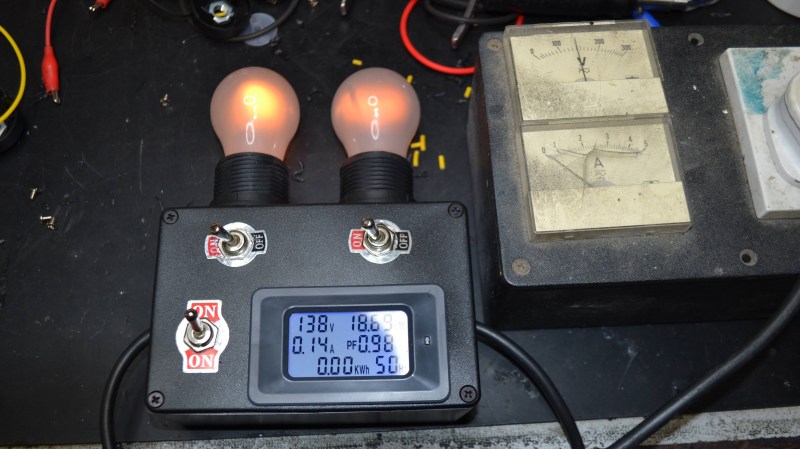
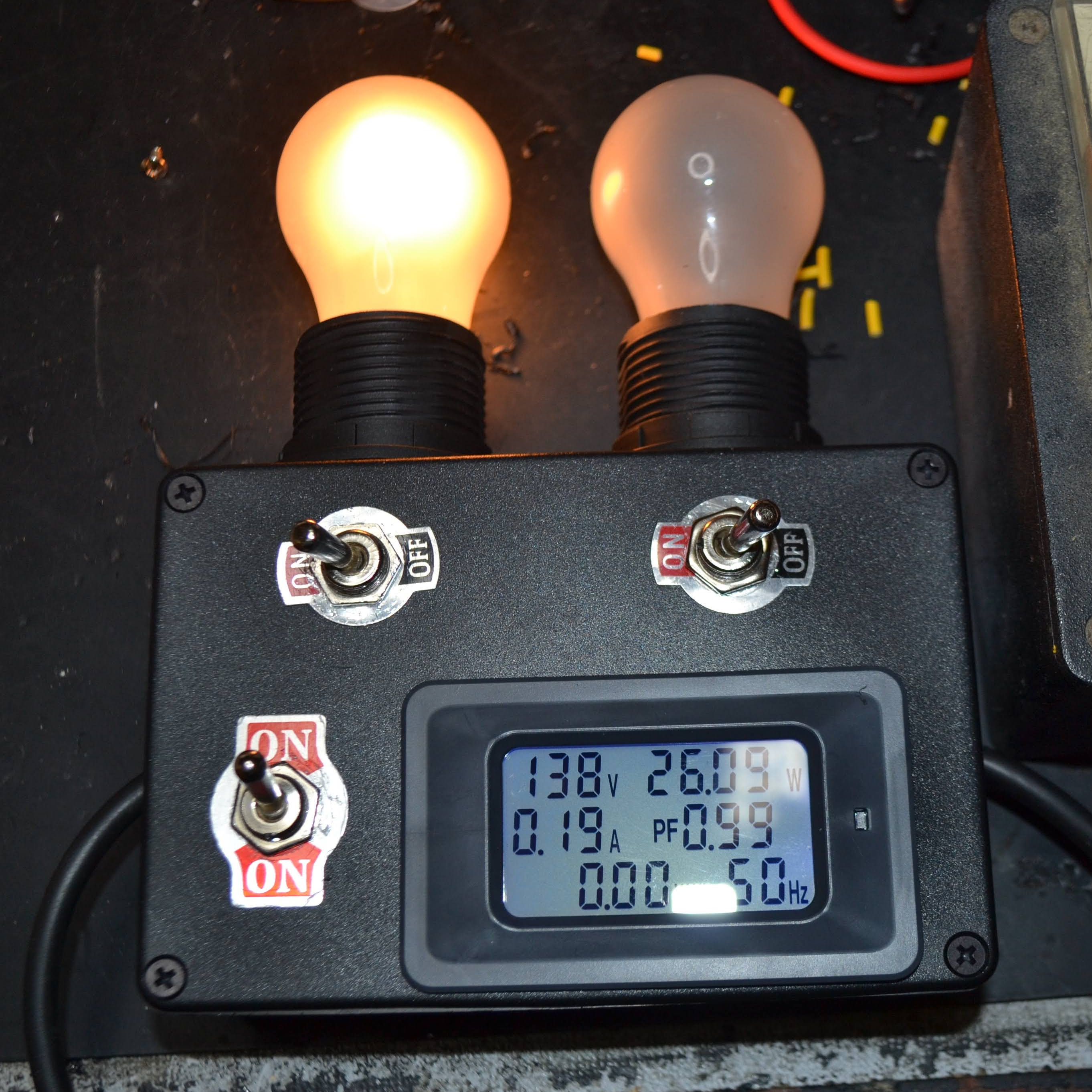
Ideally, one uses a bulb with a wattage rating that is roughly equal to the power consumption of the device being tested. If all is well, the bulb will glow very faintly and the device will work normally. A brightly glowing bulb would indicate excessive current draw. To allow some flexibility, [Doz]’s tester design allows using one or two 60 W incandescent bulbs in series, and even incorporates an inexpensive power monitor.
A dim-bulb tester isn’t an in-depth diagnostic tool but it is effective, simple, and allows for a safe startup even if there’s a serious problem like a short. It helps protect valuable hardware from going up in smoke. In fact, the fundamental concept of limiting power to protect hardware in case of a fault has also been applied in the world of retrocomputing, where it helps protect otherwise irreplaceable hardware if something goes wrong.


These are great devices with a long history for all sorts of curbside and dumpster rescues. Only trouble is, it’s getting harder to find ( in California) things like incandescent bulbs and linear power supplies. You can’t even buy an adjustable lab power supply ( except of course from the usual places that will also sell you a 5W handheld laser pointer) or a halogen spot light except for a flashlight. Which I will then need to hook up to my crummy switching lab supply to shine at a cheap spectrometer.
Wouldn’t a big enough power resistor actually be better than the bulb, because you get more control of the resistance(Wheras incandescent varies a lot with current as the filament heats, and a cold filament offers very little resistance)?
+1
What you’re describing is exactly why an incandescent lamp makes a fine charging regulator, too!
You can safely charge a 12v lead battery with just a simple 12v lamp (say, halogen lamp from your desk lamp) in series.
If the batrery is charged, the charging power goes away and the lamp gets dim.
It’s totally failsafe, no complicated microcontroller nonsense needed. Just ingenious and elegant due to its simplicity.
Too bad this technology is being eradicated by followers of the LED/solidstate cult. 🙄
The advent of easily programmable digit circuits ahs killed the analog KISS principle… Good point!
It’s not a cult, if we hadn’t switched most of our lighting from 90% inefficient incandescent bulbs to 90% EFFICIENT LEDs, we would have rolling blackouts since we haven’t built new plants or strenghthened the distribution system to handle the increased population…
You’d need a big enough _variable_ power resistor – they’re expensive and inconvenient. And at that you would still have no protection against a short that develops after you’ve turned the resistance down, whereas he non-linear resistance of the bulb will at least limit the duration of the excessive current. Plus, the bulb gives an immediate visual indication of what’s happening.
In more critical applications I combine a bulb in series with a Variac. That allows me to bring up the voltage slowly, to give electrolytics a chance to adjust, and still provides the over-current protection of an incandescent bulb.
Hair dryers have powerful heating elements with exposed heater wire. With alligator clip you have instant high power variable resistor.
No. The light bulbs have the benefit of having a PTC response. Resistance goes up when current goes up, so it has a stronger power limiting effect.
Besides that you have a visual indication of variations in current draw.
It will kinda work with resistors, but it is not as convenient.
Sooo… buy a PTC resistor?
Finding one that can handle 100 Watts is difficult and costly.
You don’t *want* them to handle 100 watts. The only reason the bulb here is burning 100 watts is because it doesn’t have a strong enough PTC characteristic. You’re using it as a combination of a PTC resettable “fuse” (*) and an indicator lamp. You already have an indicator, so use a better PTC fuse. The benefit of a higher PTC characteristic is that in a non-trip state it drops the voltage negligibly. The downside is that it means that the start is a bit harsher, but honestly if it fails with a PTC with appropriate power rating it’d probably fail with a bulb anyway.
A PTC fuse which can handle an amp at 110 VAC steady-state but which only burns a watt at trip is sub-dollar with great availability.
(*: it’s not a fuse, it’s just what some manufacturers/distributors call them)
Nothing better than 100W bulbs. Here we have tried every possible options (PTC, resistors, leds…) We are 50 electronic technicians, each of us have 6 bulbs (2// for each phase) And that’s juste the perfect device. And a wired remote to shunt them.
Fast, economic and efficient!
I guess I’m thinking too digitally, I’ve never done anything with vintage analog gear, and I don’t tend to do a lot of work with AC power.
On newer stuff with DC input PTC isn’t great, because it’s not instant and a lot of issues on the DC side of things will probably do their damage within milliseconds. It will stop a fire but probably won’t save a microcontroller, whereas in some cases you can get a fixed resistor just right so it can power your circuit with a few mA but not blow anything if you have a solder blob from 5v to an IO.
Anyone know why my DBT won’t light up at all on a non working amp that was given to me. Kenwood KA-4002. The DBT is working perfectly but I get NO light at all.
Non-California has cellars with incandescents in moldy boxes full of spiders. I hoard all sizes from those #47 pilot lights, grain of wheat, and up. Put one in series with a charger or other source and it will save both the source and the load from damage, if properly sized. A resistor takes power cold or hot, but a lamp minimizes loss when it’s cold and non-limiting. A bulb also indicates power draw and shorts.
“A resistor takes power cold or hot, but a lamp minimizes loss when it’s cold and non-limiting.”
In this case, where you’ve already got an readout (although bulbs look cool and provide a quick indicator) you can just use a PTC resistor for the same effect.
“Only trouble is, it’s getting harder to find ( in California) things like incandescent bulbs”
Just design it for an appliance bulb. Incandescent bulbs will still be common there for a long time.
Here in Indiana (and on Amazon) you can still order all the halogen incandescent lights you want. I presume they’d work fine in this use.
Halogen bulbs really only work well at full voltage and when allowed to reach full operating temperature. Run for short times or at reduced power, the filaments evaporate and plate to the inside of the glass.
I think you’re misunderstanding something here. When you use a light bulb as a ballast during testing, it only runs briefly, it’ll never run long enough for longevity to be an issue. These bulbs aren’t sitting there partially lit for hours.
I’ve built a dim bulb tester box with enhanced features. Up to 4 switchable parallel bulbs, an isolation transformer (mandatory !), a resettable fuse, some din rails with ac outlets and ampmeters, possibility to bypass the bulbs and isolation transformer, and of course a Variac to feed the beast. I can now comfortably work on my tube radios where security is absolutely needed.
Running a series incandescent lamp in the main lead is an old very good idea. But, as pointed out above, these lamps are getting hard to find. A work around can be done by using 2 mains to 12V power transformers back to back, and connect a 12V headlight lamp in the 12v line between the transformers. This has the added advantage of mains isolation.
2 x 24V transformers could also be used and select truck 24V headlight lamps.
More or less impossible to find. Haven’t seen one in stores for years now, and any online sellers say no stock.
Mains to 12V power transformers – easy to find, they are commonly used in high-end audio power amps or in linear DC supplies to power affordable car sound systems indoors, look for toroidal transformers. 12V headlight lamps, plenty available as long as you use halogen [1], old style incandescent headlamps are still available new [2], old style headlamps still available by the millions in pull-it-yourself junkyards.
1. Search: 12V auto headlamp
https://www.amazon.com/s?k=12V+auto+headlamp&crid=3LZJOJBPGCIPX&sprefix=12v+auto+headlamp%2Caps%2C113&ref=nb_sb_noss
2. Philips 4411C1 Standard Incandescent Sealed Beam headlamp, 1 Pack, 4.6 out of 5 stars 1,210 ratings, $10.30
https://www.amazon.com/PHILIPS-4411C1-Standard-Incandescent-headlamp/dp/B00R57WD2Y
Dim bulb testers can *damage* equipment, especially anything with a switch mode power supply – i.e. many things designed in the last 50 years.
SMPSs are, if you think about it, constant power *output* devices; they are designed to supply the same Vout & Iout whatever the input voltage is doing.
So obviously if the input voltage falls, to keep the output power constant the input current must rise. Too high an input current can damage the switching transistors and won’t do the input capacitors and inductors any good either..
Summary: using dim bulb testers without understanding is not much better than cargo cult science.
With a lamp in series, the current is inherently limited by the rising lamp resistance so the above damage does not apply.
Running with a lamp is just for initial testing and not for operation anyway. I have never damaged a device with this test setup, but have saves much smoke. It is a very handy test tool, one that I would highly recommend. And having a mains isolation transformer too!
I don’t think you fully understand how smps work…
You wouldn’t be using one of these on new electronics. We’re talking about bringing up old tube amps and such. I built one into my variac.
Also you don’t know how a switching power supplies work. No they are not constant power output devices. They just chop up the input voltage and smooth it out so that it holds at an output voltage, meaning they are very flexible with input voltage.
The original comment isn’t insane, but mostly irrelevant (as you’re noting) and poorly worded – it should say that switching supplies are (nearly) constant power *input* devices. All (ideal) regulators are constant power *output* devices with respect to input voltage, that’s what it means to be a regulator. The point is that switching supplies aren’t constant *source* current with respect to source voltage like a linear supply is.
With a linear supply, as the source voltage drops, the load current stays exactly the same. All that happens is the power burned in the regulator drops. With an ideal switching supply, the source current is inversely proportional to source voltage.
So if the switching supply is designed like an idiot without an undervoltage lockout (or not sized to accept basically all input), you can blow things up by lowering the input voltage such that it tries to draw too much input current than the regulator can handle. Go ahead – ask me how I know this can be a problem. Sigh.
Linear regulators are actually more tolerant to input voltage variations, other than the whole “give me too much voltage and I’ll get too hot” but everything blows up with higher voltage at some point.
The better takeaway is probably “make sure you understand the input requirements of the equipment you’re testing,” which is always a good recommendation.
That’s not necessarily true. When I was repairing treadmill motor controllers I would often put a bulb in series with the supply line. It saved me some grief on several occasions, and sometimes it would even prevent the (expensive) IGBT output modules from blowing up. I’ve also used the series bulb trick on the occasional solid-state audio amplifier.
“Dim bulb testers can *damage* equipment, especially anything with a switch mode power supply – i.e. many things designed in the last 50 years.”
Please don’t lie. Please. It’s 20 or 25 years merely.
Transformer-based power bricks with a linear voltage regulator were still sold in the 1990s. Super markets sold them, even. And not just as New old Stock, even. They were freshly made at the time. At least here in Europe.
We also used NiCD battery packs still, with NiMH types becoming increasingly popular.
It was late 90s/early 2000s when switching-PSUs and Lithium Ion (*yuck*) rechargeables began to dominate everything.
That’s when portable games consoles like the GBA started to switched from standard AA batteries over to their proprietary accu (GBA SP).
Switching-PSUs were used in IBM style PCs for a long time before already, yes. But that’s really an exception.
CB-Radios and lab equipment still used (and continue to use) good transformer-based 13,8V PSUs (deliver about 3A at constant use, 5A for a short period).
Nowadays, there are also cheaper switching-based 13,8v PSUs, of course, but they’re being used only if a high current is absolutely required and power quality is secondary.
Because, transformer-based PSUs are quality items. They’re expensive (in price) at a rated power draw for 20A-30A. But they’re worth it. They have a very clean output nearly without any RF, ripple etc. They also can withstand shorts and over-surge.
That being said, for the sake of fairness, quality PSUs on transistor basis do exist. *However*, the amount of extreme filtering needed to make them high-quality does result in a similar price tag to an expensive, but fine traditional transformer-PSU.
Higher power efficiency is the only thing a switching-PSU can provide over a traditional PSU.
A switching-PSU is nothing but a strong jammer device by nature. It’s a transmitter+a crystal radio.
Making it “clean” is more complicated than just using a classic PSU that’s clean all by itself. Vy73s, Joshua
My practical experience with SMPS as used in televisions in the ’80s when I was still a consumer electronics tech: A series lamp works just fine testing them.
It just depends on the design. If there’s no undervoltage lockout or the caps or pass transistors aren’t oversized to handle the higher ripple current at lower voltage, it’d be bad. Also depends on the lamp, obviously: if the lamp’s like a quarter the power rating of the device in question, you’re not dropping the overall voltage that much.
Of course, a design that’d fail in that situation could also fail if mains voltage sags, so it’s a crap design overall.
“dendad says: November 14, 2022 at 2:08 am With a lamp in series, the current is inherently limited by the rising lamp resistance so the above damage does not apply…I have never damaged a device with this test setup, but have saves much smoke..”
What guarantee is there that any current limiting is below that which will harm SMPS components? While I’m pleased that you have been lucky so far, will that be the case in the future?
“And having a mains isolation transformer too!”
They can reduce some risks, but too many people believe (not think!) that it they are effectively a panacea. Start by considering the interaction between an isolation transformer and an ELCB/RCD in various fault modes – and then you’ll understand that isolation transformers *increase* some realistic risks.
>>What guarantee is there that any current limiting is below that which will harm SMPS components?
There is no such guarantee. But I CAN guarantee that if the SMPS is damaged by the amount of current that it manages to draw through a series light bulb, it will certainly also be damaged by the current that it draws WITHOUT the bulb. The bulb does no harm, and offers protection in many circumstances.
Love it when I learn something, doubly so when it’s two things. I’d never heard of this type of device, and I’d never heard the term “Cargo Cult Science”. Thanks HaD and commenters.
A puff of smoke, a flash of light and a mighty ” Hi Ho, Silver, ‘Away’……”
If you can’t find an incandescent bulb, a “T” connector with the power line and a Weller soldering gun works really well. The dual power gun works the best where you pull slightly on the trigger for low powered devices, and fully pulled, testing higher powered units.
There is an enhancement in using a filament bulb. At low currents (and low illumination from unit power flow) the resistance of the filament is very low (could be 1/5 of heated value) and for devices with low quiescent power, it permits a temporary current surge which helps switched mode power supplies to whine up or power caps to do the initial higher current charge.
Make sure you are interrupting power on the high side of the power line and for the initial turn on, and that your DUT is totally air-gapped from all other devices, cables, scope probes, grounds, etc. If you are suspecting a power supply issue, it could come with an isolation fault which could blow up fancy test equipment. One hand in pocket and one on the soldering gun or switch.
Big Dim Bulb Tester with Variac and Isolation Transformer
https://www.youtube.com/watch?v=51mjt9nFoeA
You people are far too safety concious. The proper way is to plug the device into a power strip or other switched power source, ask the significant other for help, and act like your busy and ask them to turn on the source. There you have it. worst case senario you get another significant other, best case, the item works. And if the item fals you blame the significant other. Fixed it for you. (sarc/)
“Joshua says: November 14, 2022 at 7:24 am “Dim bulb testers can *damage* equipment, especially anything with a switch mode power supply – i.e. many things designed in the last 50 years.”
Please don’t lie. Please. It’s 20 or 25 years merely.” Transformer-based power bricks with a linear voltage regulator were still sold in the 1990s. Super markets sold them, even. And not just as New old Stock, even. They were freshly made at the time. At least here in Europe.”
You need to take a critical thinking course. Just because linear supplies were still made in the 90s, doesn’t mean SMPSs weren’t available before.
I have many pieces of equipment designed in the late 60s and early 70s that use SMPSs. By most people’s definition those are “vintage”.
“It was late 90s/early 2000s when switching-PSUs and Lithium Ion (*yuck*) rechargeables began to dominate everything.”
So what? SMPSs were common before; in many instances they were standard by the early 80s, due to their reduced power and weight.
Snipped several of your examples showing you have a limited experience of equipment, and are then incorrectly generalising your experience.
“A switching-PSU is nothing but a strong jammer device by nature. It’s a transmitter+a crystal radio. Making it “clean” is more complicated than just using a classic PSU that’s clean all by itself. Vy73s, Joshua”
False, except in the case of crap SMPSs.
Could you please explain why I have several pieces of extremely sensitive RF test equipment containing SMPSs, e.g. (off the top of my head) Tek 492, H8562.
(It sounds like you are a radio ham “Vy73s”, so you really ought to know about that class of equipment)
I gather some tv sets had a level of switching supply, at least in the transistor era.
And one just needs to look at early home computers, huge power transformers. That’s why the Apple II, in 1977, used a switching supply. As I’ve said before, they had to get someone with experience to design it, and it was one of the earliest switching supplies in consumer electronics. But they were in non-consumer before that.
It’s easy to power a CB set with a linear supply, 5W maximm input. But once the move to transistors, current demand went up in ham equioment.
Work has been done to reduce noise from switching supplies. Better shielding, and one commmercial supply had a knob to adjust the frequency, if it was interfering.
Too many hams live in the past, and haven’t kept up to date with technology.
Kermit’s the man!!!! https://www.arrl.org/news/view/amateur-radio-sleuthing-pins-down-source-of-strange-rf-interference
I remember a letter in QST in the early seventies. An annoying case of interference, but it was intermittent. Finally tracked down, it was a radio scanner radiating too much. It wss irregular because it was flipping channels, and stayed if there was a signal.
This was the days when scanners needed a crystal for each channel.
Michael, thanks for stabbing me in the back. Being your trophy is a honor to me. 😁
The Apple II may have been using a transistor PSU, yes. But Apple always tried to be on the cutting edge, anyway.
The Apple IIe (?) had an unstable switching PSU, also. Not a great user experience.
Other 1970s platforms also used transformers. Altair 8800, IMSAI 8080, Commodore PET, TRS-80 (in monitor)..
80s/90s (examples): The ZX81 with its external power brick, the NES/SNES game comsoles with their AC bricks (here in Europe, at least; the consoles have bridge rectifiers), the Sega Master System/Mega Drive with their external DC bricks, various home computers.
Anyway, I’m happy for you that you found in Tom another fellow that has a similar mind set and attitude. Team work and friendship are a great thing. 🙂👍
“Could you please explain why I have several pieces of extremely sensitive RF test equipment containing SMPSs, e.g. (off the top of my head) Tek 492, H8562.”
Well.. Lab equipment has special requirements, anyway. 🤷♂️ So it is expected to have specially made PSUs, as well. It’s not not exactly consumer technology, though. Rather the very opposite.
In the 90s, transformers were still a common technology in daily life. That’s all I said or meant to say. Your comment made it sound as if it wasn’t. Well, at least that’s how it did sound to me.
But maybe that was a misunderstanding. If so, then I do honestly apologize for my mistake. To err is human, after all. vy73s
“(It sounds like you are a radio ham “Vy73s”, so you really ought to know about that class of equipment)”
Or maybe I’m a humble CB operator?
I’ve mentioned a CB radio PSU, after all. ;)
>>>Joshua says:November 14, 2022 at 1:13 pm
“Could you please explain why I have several pieces of extremely sensitive RF test equipment containing SMPSs, e.g. (off the top of my head) Tek 492, H8562.”
Well.. Lab equipment has special requirements, anyway. 🤷♂️ So it is expected to have specially made PSUs, as well. It’s not not exactly consumer technology, though. Rather the very opposite.’
You are close to “there’s no such thing as a true Scotsman” territory, ever narrowing your statements when they are disproven.
How does that apply to my Tek 1502, which is designed to be used In heavy rain, and can be stored under 1ft of water? It has an SMPS.
>>>”In the 90s, transformers were still a common technology in daily life. That’s all I said or meant to say. Your comment made it sound as if it wasn’t. Well, at least that’s how it did sound to me. ”
You are in Humpty Dumpty territory there. I commented on what you did write, not what you meant to write.
>>>”But maybe that was a misunderstanding. If so, then I do honestly apologize for my mistake. To err is human, after all. vy73s
“(It sounds like you are a radio ham “Vy73s”, so you really ought to know about that class of equipment)”
Or maybe I’m a humble CB operator?
I’ve mentioned a CB radio PSU, after all. ;) ”
Apology accepted, of course :)
I don’t know anything about CB, other than what can be seen in some awful late 70s exploitation movies!
“Michael Black says: November 14, 2022 at 8:23 am Too many hams live in the past, and haven’t kept up to date with technology.”
E.g. some RF equipment from the early 80s :)
I was thinking those outraged that SSB took over from AM, even though they were licensed after SSB was dominant. The ham who said “we shouldn’t be using technology that didn’t exist in Armstrong’s time”. Someone telling a newcomer the only good handbook is from the thirties. Too many building tube gear. Even among those building solid state, some won’t use ICs or synthesizers.
It’s 101 years since the Transatlantic Test proved shortwave was useful. I’ve been licensed for fifty years, I saw synthesizers and cheap frequency counters arrive, and receivers that upconverted. And much of that fifty years is ignored. Everything I know came from reading magazine articles.
SSB is just broken AM, nothing to brag about.
In fact, SSB has poor audio quality. It hasn’t been improved in ~50 years. What a shame.
And there’s always a difference between the sender/receiver station. Not even super stable DDS/PLL driven radios did fix that. Instead, the operator must guess how his pal sounds. How professional.
So we still listen to Donald Duck and Mickey Mouse on shortwave. Or Duffy Duck, hi.
Maybe a GPS or atomic-clock controlled synthesizer is needed on both sides too *finally* fix that?
AM didn’t have that issue. It had a carrier wave to lock onto. An AFC could even follow a radio station that’s drifting.
If SSB wasn’t stripped of its carrier completely, but still had a lowered/greatly surpressed carrier, we would have had gotten the best of both worlds.
Maybe.. Maybe SDR technology can retro-actively fix this issue. SDR transceivers could do all sorts of modulation types in theory. Including, eSSB, DSB, SSB with lowered carrier, or DSB in stereo (using upper/lower half for left/right microphones; or data+voice).
AM.. Most of the better AM receivers can demodulate both FM and SSB/CW.
A BFO can add a carrier wave back into the signal. Synchronous AM receivers do the same, essentially, just better.
A regenerative receiver from early 20th century can do receive CW/SSB, too.
And in the early days of radio communications, SSB/CW weren’t needed, by the way.
Spark gap transmitters used damped waves, not undamped ones (which CW belongs to, too).
The Titanic used Morse telegraphy, but not CW. It’s a small but significant difference.
>> jenningsthecat says: November 14, 2022 at 9:57 am >>What guarantee is there that any current limiting is below that which will harm SMPS components? There is no such guarantee. But I CAN guarantee that if the SMPS is damaged by the amount of current that it manages to draw through a series light bulb, it will certainly also be damaged by the current that it draws WITHOUT the bulb. The bulb does no harm, and offers protection in many circumstances.
Please provide justification for your bald unquantified assertion.
“Please provide justification for your bald unquantified assertion.”
Alright ol’ boy, so you expect others to do things which you aren’t willing to do yourself in the very same situation ? 🙃
“There is no such guarantee. But I CAN guarantee that if the SMPS is damaged by the amount of current that it manages to draw through a series light bulb, it will certainly also be damaged by the current that it draws WITHOUT the bulb.”
This isn’t true. At lower input voltages (which is what it will see with a series bulb!) it’ll try to draw more current at the input stage, which can blow out the input caps and pass transistors.
Of course, you could say that such a design could still blow up if mains sags for some reason, and you’d be dead on right there, too.
I built one of these lightbulb current limiter it works well I still have a box of old filament bulbs that are now obsolete good for use when testing old valve radios and test equipment
It’s the perfect of option. 2 parallels 100W bulbs per phases.
Enough power to turn power supplies and direct visualisation of the current!