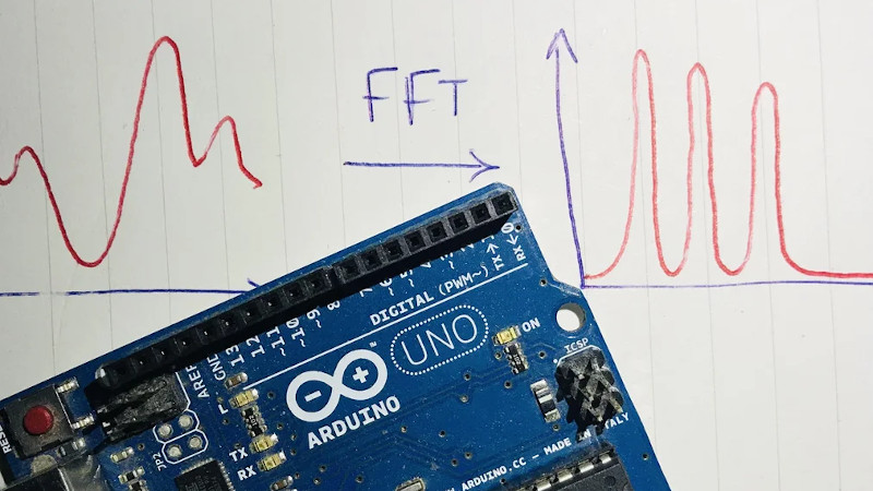
An interesting aspect of time-varying waveforms is that by using a trick called a Fourier Transform (FT), they can be represented as the sum of their underlying frequencies. This mathematical insight is extremely helpful when processing signals digitally, and allows a simpler way to implement frequency-dependent filtration in a digital system. [klafyvel] needed this capability for a project, so started researching the best method that would fit into an Arduino Uno. In an effort to understand exactly what was going on they have significantly improved on the code size, execution time and accuracy of the previous crown-wearer.
A complete real-time Fourier Transform is a resource-heavy operation that needs more than an Arduino Uno can offer, so faster approximations have been developed over the years that exchange absolute precision for speed and size. These are known as Fast Fourier Transforms (FFTs). [klafyvel] set upon diving deep into the mathematics involved, as well as some low-level programming techniques to figure out if the trade-offs offered in the existing solutions had been optimized. The results are impressive.
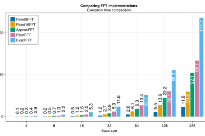
Not content with producing one new award-winning algorithm, what is documented on the blog is a masterclass in really understanding a problem and there are no less than four algorithms to choose from depending on how you rank the importance of execution speed, accuracy, code size or array size.
Along the way, we are treated to some great diversions into how to approximate floats by their exponents (French text), how to control, program and gather data from an Arduino using Julia, how to massively improve the speed of the code by using trigonometric identities and how to deal with overflows when the variables get too large. There is a lot to digest in here, but the explanations are very clear and peppered with code snippets to make it easier and if you have the time to read through, you’re sure to learn a lot! The code is on GitHub here.
If you’re interested in FFTs, we’ve seen them before around these parts. Fill your boots with this link of tagged projects.


I’m not sure I understand how Fast Fourier Transform (as in Cooley-Tuckey algorithm) is an approximation or a “real” Fourier transform of a discrete signal… The algorithm gives an exact solution of a discrete Fourier transform, the “fast” comes from the fact that it use O(n log n) operations instead of O(n²) using a clever divide-and-conquer idea.
Granted, you can indeed speed up the implementation (lowering the prefactor) by using tricks at the cost of precision on top of this (floating point values are never exact to begin with anyway), but the “fast” doesn’t come from there.
The FAST transform is a specific condition where the signal can be treated as periodic. As most of real signals are not periodic, we use windowing to make them possible to be treated as periodic with no hard issues.
The name Fastest Fourier Transform in the West is already used by libfftw. Even if libfftw is slower, you shouldn’t reuse the name.
I wasn’t aware of that – Thanks for the heads-up
Heh, when I saw the title, I thought it was a port of libfftw as well.
I second that, in fact libfftw is just about the reference implementation these days.
I almost passed the article, as I already know, and use, the very common fftw implementation.
The Fast Fourier Transform (FFT) is a specific algorithm for efficiently computing the discrete Fourier transform. FFT is not about the tradeoffs of small microcontrollers and it’s not imprecise, it’s about the asymptotic complexity of the task. The article seems to suggest otherwise.
yes. in fact when i was learning the algorithm i wrote a program that proved the only difference from ft and fft was the removal of redundant math operations that were exactly identical.
All very well, but ArduinoFFT has been around for ages, and according to the graphs in the corner, is getting on for twice as fast again as the fastest of these (6.32ms for a 256-bin transform, and another 1.49ms to window the input, and reorder & reformat the output into linear 8-bit results). It’s here: http://wiki.openmusiclabs.com/wiki/ArduinoFFT
There’s also the Fast Hartley transform, which makes use of a different kernel function – one which allows it to function as its own inverse – and is about twice as fast again. Unsurprisingly its URL is http://wiki.openmusiclabs.com/wiki/ArduinoFHT
Thank you for this, I was not aware of the tricks used by ArduinoFFT (I started this project mainly because I found the results in the first instructables weird). Now I want to try them myself!
That’s a really nice like – thanks ‘just passing’ – the links from that site are also gold. I have never implemented an FFT on an MCU and the linked Czech site had the most comprehensive and practical overview I’ve read to date. But also thanks Klafyvel for your contributions.
In his blog at https://klafyvel.me/blog/articles/fft-julia/#optimization_of_trigonometric_functions
he compares his results with fftw library. The execution time is similar, but the memory footprint is much improved, which is a big optimization for smaller systems like the Arduino. I think his approach is very interesting.
I have been told repeatedly on this web site by multiple people that Arduino users should not concern themselves with floating point issues.
“Arduino” now includes multi-core ARMs with hardware floating point.
This actually got me wondering: What’s the cheapest microcontroller with an FPU? Is it one of the squillions of Cortex-M4F chips out there, or one of the ESP32s – or something I’ve not heard of?
The article doesn’t seem to entirely cover it, how well would this perform for doing a real-time FFT on an incoming analogue signal? I’ve seen arduino code putting the AVR’s ADC in free running mode which does a homodyne detection to see if a given frequency of input wave is present, could this be used in a similar way to realtime (averaged over last few ms perhaps) detect which frequencies are present. What would be the fastest frequency it could actually see?
Hi! That’s actually my next project, I’ll most likely document it on my blog if it gives something interesting. (but first I want to try out some possible improvements pointed out in the comments)
Look up the Goertzel algorithm. It does this exact function of detecting specific frequencies.
The easiest way to detect individual frequencies very, very quickly is with Goertzel’s Algorithm!
https://www.embedded.com/the-goertzel-algorithm/
In the comments below the simple POV device article posted earlier this month I mentioned using RF induced noise on the A2D pin as a periodicity detector for syncing the POV scan rate, well this fast FFT code may be very useful for that. N.B. it doesn’t have to be that fast as we can assume that the fan blade the POV device is mounted on is mostly constant, except when switched between speed levels so the interval between timing checks can be fairly long, it just helps if these interruptions are as short as possible.
Just for giggles, let’s say I had an audio signal that I arbitrarily wanted to purge the third most significant harmonic from. Would any of these FFT implementations allow me to sense the top x harmonics, and select a filter that would feedback a portion of the signal that had been filtered to the frequency of that harmonic, so that it disappeared from the output waveform? Maybe I wanted to Add a filtered out copy of the 4th harmonic, or something like that. The analog filter could be an single Op-amp band pass filter where analog switches were used to switch in/out capacitors of an RC pair in the feedback path of the op-amp circuit.