Over at Quanta Magazine [Shalma Wegsman] asks What Is the Fourier Transform?
[Shalma] begins by telling you a little about Joseph Fourier, the French mathematician with an interest in heat propagation who founded the field of harmonic analysis in the early 1800s.
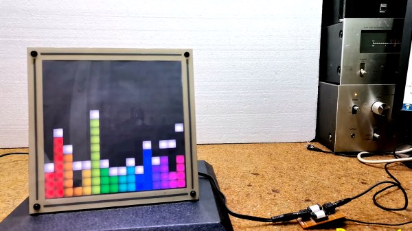
Fourier’s basic insight was that you can represent everything as a sum of very basic oscillations, where the basic oscillations are sine or cosine functions with certain parameters. [Shalma] explains that the biology of our ear can do a similar thing by picking the various notes out from a tune which is heard, but mathematicians and programmers work without the benefit of evolved resonant hairs and bone, they work with math and code.
[Shalma] explains how frequency components can be discovered by trial and error, multiplying candidate frequencies with the original function to see if there are large peaks, indicating the frequency is a component, or if the variations average to zero, indicating the frequency is not a component. [Shalma] tells how even square waves can be modeled with an infinite set of frequencies known as the Fourier series.
Taking a look at higher-dimensional problems [Shalma] mentions how Fourier transforms can be used for graphical compression by dropping the high frequency detail which our eyes can barely perceive anyway. [Shalma] gives us a fascinating look at the 64 graphical building blocks which can be combined to create any possible 8×8 image.
[Shalma] then mentions James Cooley and John Tukey and the development of the Fast Fourier Transform in the 1960s. This mathematical tool has been employed to study the tides, to detect gravitational waves, to develop radar and magnetic resonance imaging, and to support signal processing and data compression. Even quantum mechanics finds use for harmonic analysis, and [Shalma] explains how it relates to the uncertainty principle. The Fourier transform has spread through pure mathematics and into number theory, too.
[Shalma] closes with a quote from Charles Fefferman: “If people didn’t know about the Fourier transform, I don’t know what percent of math would then disappear, but it would be a big percent.”
If you’re interested in the Fourier transform and want to dive deeper we would encourage you to read The Fastest Fourier Transform In The West and Even Faster Fourier Transforms On The Raspbery Pi Zero.
Header image: Joseph Fourier, Attributed to Pierre-Claude Gautherot, Public domain.