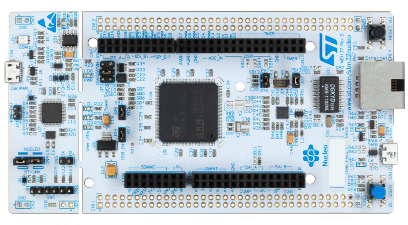
[Sergey Lyubka] put together this epic guide for bare-metal microcontroller programming. While the general concepts should be applicable to most any microcontroller, [Sergey]s examples specifically relate to the Nucleo-F429ZI development board featuring the ARM-based STM32F429 microcontroller.
In the realm of computer systems, bare-metal programming most often refers to programming the processor without an intervening operating system. This generally applies to programming BIOS, hardware drivers, communication drivers, elements of the operating system, and so forth. Even in the world of embedded programming, were things are generally quite low-level (close to the metal), we’ve grown accustomed to a good amount of hardware abstraction. For example, we often start projects already standing on the shoulders of various libraries, boot loaders, and integrated development tools.
When we forego these abstractions and program directly on the microprocessor or microcontroller, we’re working on the bare metal. [Sergey] aptly defines this as programming the microcontroller “using just a compiler and a datasheet, nothing else.” His guide starts at the very foundation by examining the processor’s memory map and registers including locations for memory mapped I/O pins and other peripherals.
The guide walks us through writing up a minimal firmware program from boot vector to blinking an LED connected to an I/O pin. The demonstration continues with setup and use of necessary tools such as the compiler, linker, and flasher. We move on to increasingly advanced topics like timers, interrupts, UART output, debuggers, and even configuring an embedded web server to expose a complete device dashboard.
While initially more time consuming, working close to the metal provides a good deal of additional insight into, and control over, hardware operations. For even more on the subject, you may like our STM32 Bootcamp series on bare-metal STM32 programming.


I have one of those, this is cool
@Eric Mockler said: “I have one of those, this is cool”
You can still buy one of those today, and they are only $24.47 USD each plus shipping.[1][2] Also, programming the STM32 NUCLEO-144 is easy in the Arduino IDE.[3][4][5][6]
1. NUCLEO-144 STM32F429ZI EVAL BOARD $24.47 242 In Stock
https://www.digikey.com/en/products/detail/stmicroelectronics/NUCLEO-F429ZI/5806777
2. NUCLEO-F429ZI STM32 Nucleo-144 development board with STM32F429ZI MCU, supports Arduino, ST Zio and morpho connectivity
https://www.st.com/en/evaluation-tools/nucleo-f429zi.html
3. Getting Started with STM32 Nucleo in Arduino IDE
https://microcontrollerslab.com/stm32-nucleo-arduino-ide-tutorial/
4. STM32Duino WiKi
https://github.com/stm32duino/wiki/wiki
5. STM32Duino Forum
https://www.stm32duino.com
6. STM32Duino GitHub
https://github.com/stm32duino
I’m so glad that there are some of these sorts of guides. Normally I feel like for most people the issue isn’t with how complex getting started is. It’s that people don’t know how to get started. The benefits are deep and wide to taking this approach. And I hope that more content comes out to help people along.
Agree
Here mixed emotions.
Glad it exists, wishing that it was with Rust.
Give it a rest
There also seems to be plenty info for rust on STM32 / cortex-M.
From youtube vid’s to git repositories and websites.
The link below seems pretty similar, but is a bit shorter.
https://docs.rs/cortex-m-rt/latest/cortex_m_rt/
https://jonathanklimt.de/electronics/programming/embedded-rust/rust-on-stm32-2/
https://blog.japaric.io/quickstart/
and many more…
“see a need, meet a need”
I’ve been trying to find time to learn Rust and Go for a few years, targeting embedded applications for both.
If I had the free time, this would be a great starting point to translate the concepts I’m already familiar with in C as a learning exercise. From what I do know of Rust, I imagine this should be really straightforward.
Maybe this is your chance to do the same? If I wasn’t neck deep in a Master’s program right now, I’d jump at the opportunity.
I just stumbled upon
“To get familiar with embedded Rust, I wrote a Tetris clone! It’s running on an STM32.”
at https://www.reddit.com/r/rust/comments/zekzij/media_to_get_familiar_with_embedded_rust_i_wrote/
(No, I’m not the author, but I gonna cross link that Reddit page to the page here)
C is the main language for embedded programming so why wouldn’t it be in C?
Rust has advantages but not as many for embedded programming, yet.
There still needs to be a lot of work done for rust to be usable for embedded programming.
Just three years ago there was a time when a very cute lady representing Farnell during “Automaticon” trade fair gave me STM32F4-Discovery and some Cortex-M3 eval board by NXP. All for free. Just because I said I was a student interested in robotics and I sometimes order parts from them. Now ARM MCUs are nowhere to be found. Also with all the lockdowns, economy failure and risk of military action from hostile countries I doubt I’ll go to Warsaw in next 5 years. Sadly I feel it’s too risky and too expensive for me.
I am neither a native English speaker nor a programmer, but shouldn’t “intergraded development tools” be “integrated development tools”?
But sadly STM32 MCU are just unavailable for the moment (about one year delay…).
Lcsc
@Henrik said: “Lcsc”
Beware of fakes.
If we lived in a sensible timeline this guide would be on ST’s website as the basic default with headers for each micro they sell.
STM Cube has its place but it also almost always breaks “old” projects with each update, having a bare metal GCC/GDB compile & debug solution readily available would be great for a lot of projects.
I really like these type of articles. I had planned on doing something like this years ago, but I came across some tutorials that were phenomenal. I learnt more about embedded systems, at least the firmware aspect from these videos than I did at university. I cannot recommend these videos enough.
https://www.youtube.com/watch?v=3V9eqvkMzHA
I’d really wish that ST would remove the ST-Links from all those nucleo boards to bring the price down and them sell them separately.
The “blue pills” are kaput unfortunately, because you never know what processor is on it and what sort of incompatibilities that introduces. I think the “black pills” with STM32F411 are still good though. But anyway, I only buy them from WeAct even though these cost a little bit more then other clones, in the hope they stay a valid product. But ST’s goal is not to deliver cheap boards to hobbyists. They want to showcase the capabilities of their processors with the nucleo boards. They also have the altium projects (for at least some of) the Nucleo boards (which is very nice of them). And when I loaded that in KiCad I saw it was a 6 layer PCB, which I found a bit strange. But I assume they know their stuff and have done the tradeoff between PCB cost and development cost.
What’s odd about a 6-layer board? One definitely could argue that a Nucleo board could be fairly easily designed with 4 layers. However, 6-layers aren’t a ton more expensive than 4-layers at scale, and is about what I’d start designing with for a mass-produced board. It allows power and/or trace planes while retaining a nearly uninterrupted ground return plane under each side, making it so that you’re much less likely to run into EMI or timing issues.
As a hobbyist, I tend to ask: can it be done with a 2 layer board?
If so, you could (in theory) make the board yourself, at home.
Once you go to 4 (or 6) layers you’re going to need a professional manufacturer. Even then, the penny pinching says a 4 layer design is the preferred solution. Not just for hobbyists either – shaving even a few ounces off in-flight magazines has been shown to produce significant savings in airline fuel costs.
For small, simpler boards, it’s possible to do all your routing on one side and have a ground plane on the opposite. It’s pretty limiting, even if you allow a few vias and very short traces on the ground side. (And at higher frequencies the impedance path for ground return is an issue with even small traces.)
But a big advantage of multilayer boards is putting ground (or power) planes on top and bottom layers and running all your traces inside, so the spiky digital or switching nodes are shielded by the power planes. There’s not much way around that with DIY boards without a LOT of effort, like, stacking double-sided boards and soldering vias, as wire or header pins, through them.
Just NO.
Don’t put the power planes on the outside of a 4 layer PCB.
4 layer PCB’s are much easier to route and are likely to improve the PCB design and reduce EMI compared t 2 layer PCB’s, but putting the GND plane on the outer layer is a bad idea for a lot of reasons.
First, you have your parts soldered on the outside, which means you can’t have a continuous GND plane anymore.
A lot of the benefits of a 4 layer PCB are from the closeness of the inner layers to the outside layers, there is just a thin prepreg between them, and this reduces the loop inductance significantly compared having the whole PCB (1.5mm) between the two layers.
Having GND on the outer layers is also horrible for fault finding and repair.
The possible extra shielding is offset by the many holes for all the pads. The goal is to reduce loop inductance, which means having a direct return path in the GND plane for each of the (digital) signals.
And it’s also not just the pads. If you put GND on the outer layer, you also need many more vias, which is also PCB real estate not available for the GND plane.
Putting via’s in the pads is another sort of nightmare, because solder will wick into the holes and can starve the pad of enough solder for a reliable connection. There are technologies such as “via in pad” or “via in pad plated over” = vippo but those come at extra manufacturing costs.
If someone wants to make PCBs at home for the fun of it, that may be a valid reason. Otherwise, professionally made custom PCBs’ prices and quality have now eliminated all other excuses. I’ve had DirtyPCBs (http://www.dirtypcbs.com/) make over 20 designs for me so far, and I’ve been quite happy with them. Many on the 6502.org forum are using JLCPCB (https://jlcpcb.com/). (I have now used JLCPCB for a couple of very small, simple boards, but not enough to have any authoritative opinion on them yet.) Others are using PCB Shopper (http://pcbshopper.com/) or PCB Way (http://www.pcbway.com/).
please translate to polish language
Also please translate to hsilop.
One effect of bare metal programming is that the code can be difficult to migrate. Processors age and or otherwise less available and migration is necessary. Use non-abstracted access to the underlying metal can require a rewrite of the code and carries all of the costs that implies.
So you program in a HAL layer instead, which somewhat isolates your main code from the bare metal.
If you use macros, it’s just as fast. Then, you only port the HAL, mostly.
Exactly. That’s why this guide starts from building HAL API, like “gpio_set_mode()”. If one migrates to the other MCU, only CMSIS / mcu.h includes change, the code in main.c remains the same.
Learning the tool set is well over 75% of the battle. SDK’s nowa days are very detailed and exhaustive. My problem is I like many different MCU’s which means I need to learn how to use many different SDK’s. I like STM CubeIDE, NXP MCUXpresso also RISCV MounRiver Studio of course GCC and Renesas E2 studio, ESP-IDF. The list goes on. I use them all. If you want to check out the most complicated SDK I have used then play around with the SDK for the RZ/A2M processor. It is for the E2 studio. I like simple and easy like STM32CubeIDE also MCUXpresso is good but not as user friendly as STM32CubeIDE . IDE’s like Atmel studio just suck.
I used this guideline.. Found useful for understading basics
Bare Metal Programming with BluePill and STM32CubeIDE
https://microdigisoft.com/bare-metal-programming-with-bluepill-and-stm32cubeide/
STM32 Blue Pill Bare Metal Programming: LED Blinking
https://microdigisoft.com/bare-metal-embedded-build-process-in-embedded-c-prograaming-with-example/
Bare Metal Embedded System in Embedded C programing
https://microdigisoft.com/bare-metal-programming-on-stm32f103-nucleo-64-using-stm32cubeide/
Bare-Metal Programming on STM32F103 Nucleo-64 using STM32CubeIDE
https://microdigisoft.com/bare-metal-programming-on-stm32f103-nucleo-64-using-stm32cubeide/