Rotary Dial Number Pad Is The Perfect Prank For Retro-Phone Enthusiast

We’re not sure about the rest of you, but to us, a keyboard without a number pad all the way over to the right just seems kind of — naked? We might not be accountants, but there’s something comforting about having the keypad right there, ready for those few occasions when you need to enter numbers more rapidly than would be possible with the row of number keys along the top of the keyboard.

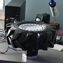
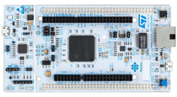
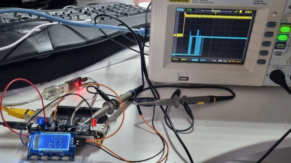
What we are sure about, though, is that rapid numeric keying is not what this rotary dial numpad keyboard is all about. In fact, it’s actually an April Fool’s prank [Squidgeefish] played on a retro-phone-obsessed coworker, and it worked out pretty well. Starting with an old telephone dial from what must be an exceptionally well-stocked parts bin, [Squidgeefish] first worked out the electrical aspects of interfacing the dial with a cheapo mechanical keyboard. It turns out that there’s a lot of contact bounce in those old dials, leading to some software hacks to keep the Arduino happy.

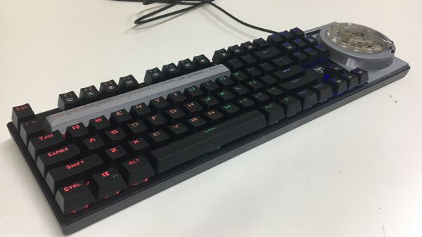
There was also a little hackery needed to stuff a USB hub into the keyboard, as well as literal hacking of the keyboard’s PCB. A 3D printed enclosure allows the rotary dial to nestle into the place where the regular numpad would be, and it looks pretty good. We also like forcing the issue by replacing the entire row of number keys with a single massive prank key.

While this was all for fun, there are a couple of cool tips here, like chucking a bit of printer filament in a Dremel tool to stir-weld parts together. And even though we’ve seen that parametric keycap generator before, it is pretty cool to see it in action.

Radial Vector Reducer Rotates At Really Relaxed Velocity

When [Michael Rechtin] learned about Radial Vector Reducers, the underlying research math made his head spin, albeit very slowly. Realizing that it’s essentially a cycloidal drive meshed with a planetary gear set, he got to work in CAD and, in seemingly no time, had a design to test. You can see the full results of his experiment in the video below the break. Or head on out to Thingiverse to download the model directly.

[Michael] explains that while there are elements of a cycloidal drive, itself a wonderfully clever gear reduction mechanism, the radial vector reducer actually has more bearing surfaces, and should be more durable as a result. Two cycloidal disks are driven by a planetary gear reduction for an even greater reduction, but they don’t even spin, they just cycle in a way that drives the outer shell, setting them further apart from standard cycloidal drives.

How would this 3D printed contraption hold up? To test this, [Michael] built a test jig with a NEMA 23 stepper providing the torque, and an absurd monster truck/front loader wheel — also printed — to provide traction in the grass and leaves of his back yard. He let it drive around its tether for nearly two weeks before disassembling it to check for wear. How’d it look? You’ll have to check the video to find out.

If you aren’t familiar with cycloidal drives, check out this fantastic explanation we featured. As for planetary drives, what better way to demonstrate it than by an ornamental planetary gear clock!

Continue reading “Radial Vector Reducer Rotates At Really Relaxed Velocity”

Nucleo-F429ZI development board with STM32F429 microcontroller

Epic Guide To Bare-Metal STM32 Programming

[Sergey Lyubka] put together this epic guide for bare-metal microcontroller programming.  While the general concepts should be applicable to most any microcontroller, [Sergey]s examples specifically relate to the Nucleo-F429ZI development board featuring the ARM-based STM32F429 microcontroller.

In the realm of computer systems, bare-metal programming most often refers to programming the processor without an intervening operating system. This generally applies to programming BIOS, hardware drivers, communication drivers, elements of the operating system, and so forth. Even in the world of embedded programming, were things are generally quite low-level (close to the metal), we’ve grown accustomed to a good amount of hardware abstraction. For example, we often start projects already standing on the shoulders of various libraries, boot loaders, and integrated development tools.

When we forego these abstractions and program directly on the microprocessor or microcontroller, we’re working on the bare metal. [Sergey] aptly defines this as programming the microcontroller “using just a compiler and a datasheet, nothing else.” His guide starts at the very foundation by examining the processor’s memory map and registers including locations for memory mapped I/O pins and other peripherals.

The guide walks us through writing up a minimal firmware program from boot vector to blinking an LED connected to an I/O pin. The demonstration continues with setup and use of necessary tools such as the compiler, linker, and flasher. We move on to increasingly advanced topics like timers, interrupts, UART output, debuggers, and even configuring an embedded web server to expose a complete device dashboard.

While initially more time consuming, working close to the metal provides a good deal of additional insight into, and control over, hardware operations.  For even more on the subject, you may like our STM32 Bootcamp series on bare-metal STM32 programming.

Trash Bag And Foam Board Hovercraft Doesn’t Fail To Succeed. Or Fail.

When you think of a vehicle that can do it all- water, land, ice, snow and more- the hovercraft often comes to mind. And while they might not be ubiquitous, hovercraft catch the imagination of many a hacker just as it has for [JamesWhomsley] of [ProjectAir]. [James] has built a small, but just big enough hovercraft as you can see in the video below the break.

Starting with a small RC proof of concept, [James] tested out some of his favorite construction materials: foam board, trash bags, duct tape, and our personal favorite: hot glue! After a successful run with the radio controlled model, [James] set out to build a hovercraft big enough to carry a human.

The resulting hovercraft was definitely enough to take a human for a spin, despite still using RC airplane parts for power. Sure, there were a couple of instances of parts going flying, foamboard being shredded, and loss of control. Even so, the trash bag air skirt stayed intact, and the aforementioned damage was nothing some tape and hot glue couldn’t fix. [James] was back on the air in no time.

Of course, some of the very reasons that we don’t see hovercraft roaming the streets come up in the video, namely off-camber paths. But the build itself is quite good, and for those of us who’ve wondered what it takes to make a hovercraft, this video shows how the sausage is made.

This isn’t the first garbage bag based hovercraft, and we featured another RC/Arduino controlled version just a while back.

Continue reading “Trash Bag And Foam Board Hovercraft Doesn’t Fail To Succeed. Or Fail.”

A dekatron-based clock with a GPS receiver and a plastic dinosaur on top

Dekatron Clock Tells The Time, Sans Semiconductors

Over the years, there have been several memory and display technologies that served a particular niche for a while, only to be replaced and forgotten when a more suitable technology came along. One of those was the dekatron: a combination memory and display tube that saw some use in the 1950s and ’60s but became obsolete soon after. Their retro design and combined memory/display functionality make them excellent components for today’s clock hackers however, as [grobinson6000] demonstrates in his Dekaclock project.

A dekatron tube is basically a neon tube with ten cathodes arranged in a circle. Only one of them is illuminated at any time, and you can make the tube jump to the next cathode by applying pulses to its pins. The Dekaclock uses the 50 Hz mains frequency to generate 20 ms pulses in one tube; when it reaches 100 ms, it triggers the next tube that counts hundreds of ms, which triggers another one that counts seconds, and so on with minutes and hours.

The Dekaclock uses no semiconductors at all: the entire system is built from glass tubes and passive components. However, [grobinson6000] also built an auxiliary system, full of semiconductors, that makes the clock a bit easier to use. It sits on top of the Dekaclock and automatically sets the correct time using a GPS receiver. It also keeps track of the time displayed by the dekatrons, and tells you how far they have drifted from their initial setting.

Both systems are housed in sleek wooden cases that perfectly fit the tubes’ retro aesthetic. [grobinson6000] was inspired to make the Dekaclock after watching another dekatron clock we featured earlier, and designed the GPS receiver to work alongside it. Dekatrons are surprisingly versatile devices: you can use them to make anything from internet speed gauges to kitchen timers.

Continue reading “Dekatron Clock Tells The Time, Sans Semiconductors”

Perhaps It’s Time To Talk About All Those Fakes And Clones

A while back, I bought a cheap spectrum analyser via AliExpress. I come from the age when a spectrum analyser was an extremely expensive item with a built-in CRT display, so there’s still a minor thrill to buying one for a few tens of dollars even if it’s obvious to all and sundry that the march of technology has brought within reach the previously unattainable. My AliExpress spectrum analyser is a clone of a design that first appeared in a German amateur radio magazine, and in my review at the time I found it to be worth the small outlay but a bit deaf and wide compared to its more expensive brethren. Continue reading “Perhaps It’s Time To Talk About All Those Fakes And Clones”

Showing the scope screen and the BeagleBone setup side by side, with GPIO input and output traces shown on the scope screen.

How Realtime Is Your Kernel? Scope A GPIO To Find Out

When debugging something as involved as kernel scheduler timings, you would typically use one of the software-based debugging mechanisms available. However, in cases when software is close to bare metal, you don’t always need to do that. Instead, you can output a signal to a GPIO, and then use a logic analyzer or a scope to measure signal change timing – which is what [Albert David] did when evaluating Linux kernel’s PREEMPT_RT realtime operation patches.

When you reach for a realtime kernel, latency is what you care about – realtime means that for everything you do, you need to get a response within a certain (hopefully very short) interval. [Albert] wrote a program that reads a changing GPIO input and immediately writes the new state back, and scoped both of the signals to figure out the latency of of the real-time patched kernel as it processes the writes. Overlaying all the incoming and outgoing signals on the same scope screen, you can quickly determine just how suitable a scheduler is when it comes to getting an acceptable response times, and [Albert] also provides a ready-to-go BeagleBone image you can use for your own experiments, or say, in an educational environment.

What could you use this for? A lot of hobbyists use realtime kernels on Linux when building CNC machine controllers and robots, where things like motor control put tight constraints on how quickly a decision in your software is translated into real-world consequences, and if this sounds up your valley, check out this Linux real-time task tutorial from [Andreas]. If things get way too intense for a multi-tasking system like Linux, you might want to use a RTOS to begin with, and we have a guide on that for you, too.