A KVM is a great tool for administering a number of different computers without cluttering one’s desk with extra peripherals, or for having to re-connect the keyboard, video, and mouse to each new machine as needed. For local administration this can save a ton of time and headache. For remote administration, though, a virtual KVM is needed, and although these solutions are pricey it’s possible to build one around a Raspberry Pi for a fraction of the cost. This one adds even more functionality by also switching the ATX signals from the motherboard and simplifying cable management to boot.
While the PiKVM that we’ve featured before does include the ability to switch these signals to remotely power the computer on or off or reset it, as well as monitor the status LEDs, this project from [vileer] simplifies the design somewhat. By using the built-in USB 3.0 multiplexer, these signals can be integrated with the USB 2.0 needed for the keyboard and mouse into the same RJ45 cable, eliminating the need for USB cables and simplifying cable management. Of course this means that the PiKVM hat won’t work the same way, so [vileer] has created a new breakout board that solves these problems as well.
A true networked KVM like this one or the PiKVM it takes inspiration from are indespensible tools, since they allow the computers not only to be reset or power cycled remotely, but also to interact with their BIOS or boot settings without having to physically access the computer. Being able to do this effectively with a Raspberry Pi has surely brought down the cost and complexity of deploying solutions like these for a lot of people.


“ATX signals” isn’t very descriptive, since ATX refers to several things. “Motherboard front panel signals” would be a little bit better. “Power & reset switches, power & HDD LEDs” would be even better.
I am having much trouble parsing this post as well.
Going to the project page and seeing some diagrams got me straightened out. Although it calls it ‘ATX signals’ as well. I would say front panel header or such.
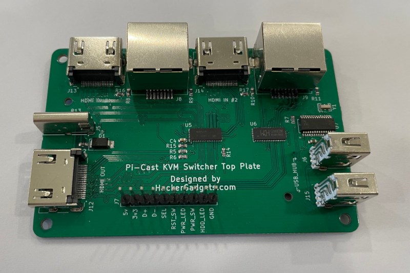
Looks like this is a set of circuit boards that connects USB and power button control over an RJ45 jack.
You could just start with that instead of confusing the heck out of us.
Interesting idea, not sure how it is in practice, not thrilled with RJ45 unless its safe to plug them into regular network jacks with no ill effect, as they will undoubtedly be cross plugged at some point.
The ‘receiver’ PCB should be shaped like an IO card so that you have a place to mount it, also make it compatible with a cheap network card backplate. You gotta think these things through.
While I’m thinking, use the standard front panel pinout so that it will be easy to wire up.
Many cases have the 2×5 block with a keying pin, most motherboards are also conforming to the standard. Doing a strange non standard pinout doesn’t make much sense. I am sure there is a reason for doing it this way, I can’t figure it out and didn’t see it on the page. Also no shots of the vertical connector; I am asssuming USB-C
The RJ45 port was not supposed to connect to the motherboards directly. The RJ45 port on the KVM switch supposes to be connected to a breakout board called “ATX control board” which will convert the RJ45 to a 2.54mm pin header. And the “ATX control board” was built to mount on the unused PCIe slot.
You can find more detail on this photo. https://hackaday.io/project/188805/gallery#8045bf908cb9a21cd538e9a33abe71bc
You are right about it. The word “ATX” is what the PiKVM project use for the motherboard panel control interface. So I just took it for my project, it’s a little hard for those who are unfamiliar with PiKVM project to figure it out.
Don’t worry about it.
People have been bleating about this concept for nearly a decade !!
https://hackaday.com/2013/05/19/atx-raspi-is-a-smart-power-source-for-raspberry-pi/#comment-1005709
Seems like stuff you could connect as a USB serial device.
“USB 3.0 1:2 multiplexer can multiplex 6 channels”
I don’t know what this means, if there was a parts list so I could find the datasheet maybe I could figure it out, still lost.
I’m sure its a great idea, of someone could tell me what the thing is actually doing.
The “USB 3.0 1:2 multiplexer” chipset I used in this project is CH483M, you can find the datasheet here at this link(http://www.wch-ic.com/downloads/CH482DS1_PDF.html). I’ve uploaded the schematic file to the project page, you could find more information on it.
Basically, the CH483M can multiplex 3 pairs of differential high-speed signals (D+, D-, SSRX+, SSRX-, SSTX+, SSTX-). I took the D+/- for the USB 2.0 multiplexing, the SSRX+/- and SSTX+/- for the ATX(or we could call it front panel control signals) multiplexing.
This’s a little overkill because the pairs that start with SS were designed for high-speed signals. But it works pretty fine under low-speed signals.
That’s pretty clever using the ‘spare’ USB3 lines as auxiliary digital I/O to add functionality to a what is essentially a USB2 multiplexer
Yes. I want a PiKVM for a server I am building. I found a fine version the fit perfectly in the space that I have. It use the Zero Pi BUT is not possible to find a Pi at a REASONABLE cost. I keep reading about Pi’s projects but every time the shortage (and COST) kill my lust to buy. If the “low cost and fast to obtain Linux board” is not more “low cost” and rare as a diamond we keep reading, dreaming, planning without making. Is the maker version of the “coitus interruptus”…
I am an engineer / hacker and as much as using RJ45 sounds like a good idea, there are plenty of other easy to use and obtain I/O port form factors. Don’t use something someone is GOING to plug into a network router or POE accidentally. Because they ARE going to. Trust me.
What you mentioned will definitely happen. In the original PiKVM hat they placed a optocoupler between the GPIO and the RJ45 port in order to isolate the signal. Maybe I should take that for may design too.
Maybe you can try M12 X-Code Connectors
Unfamiliar with what an M12 X-Code Connector is, I looked it up:
https://www.te.com/en/products/connectors/circular-connectors/intersection/m8m12/m12-x-code.html
Yes, M12 XCODE is often used for Ethernet in industry, but sometimes it is also used for other signal transmission. Since this interface is not common in the civilian field, people who are familiar with this interface have certain professional knowledge. Network cables using this interface can be purchased directly on the market, and the characteristic impedance should not change, so only a small part of the design needs to be changed.
Or other general industrial connectors, which can improve the reliability of the connection while further ensuring safety.