We’ve seen our share of custom PCBs here on Hackaday, but they aren’t always pretty. If you want to bring your PCB aesthetics up a notch, [Ian Dunn] has put together a guide for those wanting to get into PCB art.
There are plenty of tutorials about making a functional PCB, but finding information about PCB art can be more difficult. [Ian] walks us through the different materials available from PCB fabs and how the different layer features can affect the final aesthetic of a piece. For instance, while black and white solder mask are opaque, other colors are often translucent and affected by copper under the surface.
PCB design software can throw errors when adding decorative traces or components to a board that aren’t connected to any of the functional circuitry, so [Ian] discusses some of the tricks to avoid tripping up here. For that final artistic flair, component selection can make all the difference. The guide has recommendations on some of the most aesthetically pleasing types of components including how chips made in the USSR apparently have a little bit of extra panache.
If you want to see some more on PCB art, check out this work on full-color PCBs and learn the way of the PCB artist.


I did pcb design for a while. Until the software for it got better in the early 90’s. Some of the boards done with hand applied tape for the “lands” were all over the place design wise. The tape had a habit of moving unless you made cuts and corners to relieve the tension in a turn. Tape a path in the morning and after lunch it had moved 0.005 inch. The heat of afternoon, the humidity…..Ah, the good old days
I can relate to doing layouts using PCBs & tape… I cut my teeth using that technology… hated every moment of it. LOL
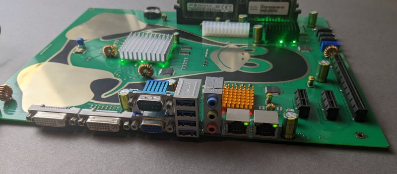
CAD software for PCB design has improved over the past 30 years but if I’d ever done a PCB layout that was “aesthetically pleasing” (i.e. as in this article’s photo of the Linux Penguin), I would have been shown the door in the most brusque of manners.
Cool, art-nouveau PCBs are nice for the hobbyist but in the real world, it just doesn’t fly.
Really must warn against the idea of exposing traces without soldermask for aesthetic reasons. PCB art is very nice, but one mustn’t let it compromise functionality, and omitting soldermask makes it all to easy to create shorts during soldering (especially where a trace runs under an SMD part), or have shorts occur during use of the board if you place it on a conductive surface. Form follows function, don’t compromise function for form.Iif you really want exposed traces then add extra traces, not electrically connected to anything (they’ll fail design rule checks in EDA programs but can export to gerber nonetheless and board houses will happily manufacture them) of the real circuit (except maybe all to ground). Well away from places where soldering is to occur, text, logos or other graphics can look very nice if done in bare copper with soldermask holes matching the copper’s shape. Most EDA programs can import images which they convert to shapes made from a series of raster lines which you can then assign to the copper and soldermask layers.
In the late 70s, youʻd see a lot of playful art on PCBs and in chips. Much of the fabrication process was manual and creative folks would play in the dead spaces. The best PCB Iʻve ever seen was a drive amp ( 8” x10” board ) from Compumotor. All of the borders and circuit free areas were beautifully decorated in an Egyptian motif. Hierogylphs, sphinxes, pyramids, jungle vines, etc.. All hidden away inside of a normally sealed drive module.
That sounds amazing. Wish I could find a photo of this.
@evilmonkeyz on instagram buys old parts … cracks them open and makes videos with a microcope of what the chip looks like inside. He is regularly snooping for art hidden by the developers that will never be seen.
Looks like Aurius PCB 61-000836-01 fits that description.
Very useful! I’ve been doing some designing of Eurorack modules, using FR4 PCBs for the front panels; the few I’ve gone ahead and had fabbed have been fairly utilitarian, mostly just labels and graphics in the silk screening. I have done one graphic in removed mask (to show the ground pour underneath), and I’ve had fabbed another person’s design which cut the pour and mask in one spot to make a sort of light pipe for an LED blow it, but the more complete exploration here of design techniques is giving me some neat ideas.
Er, that’s ”LED below it”.
While modern EDA, such as KiCad have gotten better at allowing artistic expression (curved traces, bitmap imports on various layers etc), I’d like to point out PCBmode – a circuit board design software written in Python, allowing arbitrary shapes for any element of the board, using stock Inkscape as the GUI.
Repo : https://github.com/boldport/pcbmode
Documentation (sparse) : https://pcbmode.readthedocs.io/en/latest/
Gallery : https://boldport.com/shop
It’s been blogged about several times here at Hackaday:
https://hackaday.com/blog/?s=pcbmode
PS : Not affiliated – except I used PCBmode many years back for a PCB art design, when KiCAD could not manage such a design elegantly.
Read the whole guide, really great stuff and very inspiring 🤪
Designing aesthetically pleasing PCBs involves several factors such as layout, color schemes, and component placement. The layout should be organized and easy to read, with clear labeling and consistent spacing.
Using a color scheme can make the PCB more visually appealing and easier to understand. Different colors can be used to distinguish between different types of components or connections.
Component placement is another important aspect of PCB design. Components should be placed in a logical and organized manner, with enough space between them to prevent overcrowding and to make it easy to identify and troubleshoot any issues.
Additionally, PCBs can have a professional finish using different surface finish techniques like Hot Air Levelling (HAL) , Immersion Gold (ENIG) etc.
It’s also worth to consider that PCBs are not only functional but also part of the product design and should align with the overall design aesthetic.
This is what AI text looks like!
Good eye! I bet this was gpt3 or whatever.
At least the bot looks to have read the OP since it keeps using specific phrases from the guide? LOL
If you are designing a board that is to be used with high frequency (read high speed digital boards or radios for instance) or switching high currents/voltages, or switching power supplies, aesthetics is a secondary concern (maybe even tertiary or lower). One poorly chosen routing and the things will fail and/or radiate noise like a broadcast antenna. Not that it can’t be artistic…but, in my designs I’ll think way harder about good ground returns, minimal radiation loops, reflections, and heat dissipation long before “pretty”.
Functionality has a beauty all it’s own. e.g. modern chips, etc.
If it doesn’t work, or is faulty, or can’t be used because it pollutes the radio frequency bands, then it is just art. If it can’t deal with heat dissipation, then it is just a pretty hand warmer that doesn’t last long, or worse, a fire hazard.
That Russian IC in the guide is a work of art on itself, I recommend reading the article just for that one picture alone!
That’s quite something
Modern pcb with smd parts look neat but the parts are less colurfull the parts have limited range of colours old through hole parts have capacitors with many colours my wife commented on this when she watched me sort my parts stock she liked the colourful electrolytic capacitors and old type c280 capacitors had stripes on them
A stupid image of a penguin is not what I think of something aesthetically pleasing.
I like the Linux Penguin :) . That said, functionality wins over art any day.
There are a wider variety of art pieces in the OP that might better suit your tastes. This was just the one that had the right aspect ratio for the header image.
If you don’t like penguins, there was another contender for the Linux mascot who’s recently had a bit of a resurgence: http://xenia-linux-site.glitch.me/
If only this had been posted before the Kickstarter ended.
I vaguely recall a circuit board from decades ago, maybe it was a General Radio signal generator or an H. H. Scott stereo receiver/amp.
The components were laid out beautifully in a circular fashion. I wonder if that made sense for the signal path, or just artistic license. (Or both!)
I’m so disappointed to learn that isn’t a real motherboard. I mean, I knew it wasn’t an Intel-compatible high end gaming rig or anything but I thought maybe it really was a homebrew Arm device. I wanted to stick it in a windowed case and re-live the late 90s only better.
i like the under-heatsink LEDs glowing,
would look rad in the dark!
at first i thought it was a real desktop mainboard too…
until i noticed it was lighting the ethernet link/activity LEDs with nothing connected,
and no power connected to the power-socket :P