You can buy gears off the shelf, of course, and get accurately machined parts exactly to your chosen specification. However, there’s something rugged and individualist about producing your own rotating components. [Maciej Nowak] demonstrates just how to produce your own gears with a homemade cutting tool.
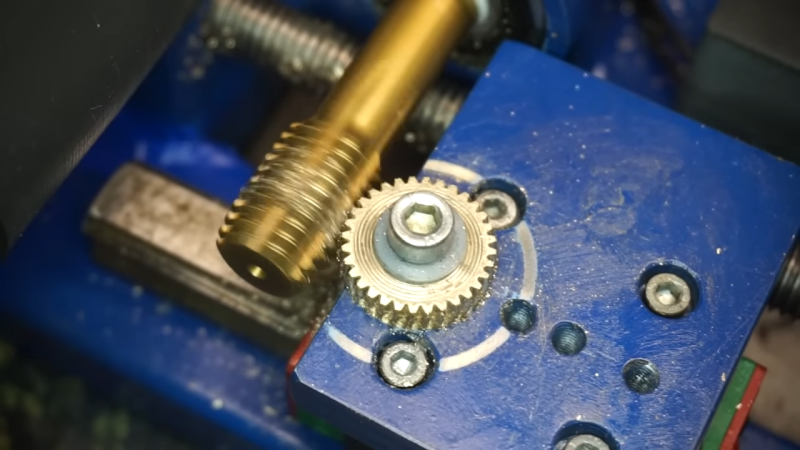
 The cutting tool for the job is an M16 machine tap, chosen for the smaller flutes compared to a hand tap. This makes it more suitable for cutting gears. It’s turned by a belt driven pulley, run by a small motor. The workpiece to be cut into a gear is then fed into the cutting tool by sliding on a linear bearing, with its position controlled by a threaded rod. The rod can be slowly turned by hand to adjust the workpiece position, to allow the gear teeth to be cut to an appropriate depth.
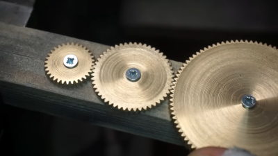
The method of action is simple. As the tap turns it not only cuts into the workpiece, but rotates it on a bearing as well. By this method, it cuts regular teeth into the full circumference, creating a gear. Obviously, this method doesn’t create highly-complex tooth shapes for ultimate performance, but it’s more than capable of creating usable brass and steel gears for various purposes. The same tool can be used to cut many different sizes of gear to produce a whole geartrain. As a bonus, the resulting gears can be used with M16 threads serving as worm gears, thanks to the pitch of the tap.
If you find yourself needing to produce tough metal gears on the regular, you might find such a tool very useful. Alternatively, we’ve explored methods of producing your own sprockets too, both in a tidy manner, and in a more haphazard fashion. Video after the break.


I’ve done this, it works, but it does bear pointing out that the result of this is gears that have slightly helical teeth with a slight depression in the center. It’s a great way to make wormgears. The involute gear shape that gear teeth are supposed to have is generated pretty nicely by this, you only need one cutter to form the whole range of gears, but the side to side tooth shape is definitely going to present some challenges for gear to gear transmission on anything other than pretty thin gears.
On the other hand, if you let them run for a while, they’ll wear in and fit better. TIL wooden gears made of pegs sticking out will eventually wear to a reasonably good low friction tooth form.
Thanks for the insight!
The ‘scribing with the caliper jaws’ trick was worth the price of admission, but it feels like something I’d have gotten my knuckles rapped for in shop class.
Still trying to figure out why it doesn’t make a couple of uneven pitches when it completes the circle. A 20mm disc is 62.8mm in circumference and the tap has a 2mm pitch.
I see that on YouTube videos so much I thought they were meant to be used that way and I just didn’t know because I’m an amateur.
They were intended to be used that way.
Getting precision from scribed lines is a dying art. CNC has eliminated the need. There are old machinist training vids on youtube that cover this in some detail.
Not with your good calipers. Using them to scribe is a way of marring your jaws and losing precision. I guess it’s fine with the cheap digital calipers that drain their battery in 5 days, or with an old set of verniers you can’t rely on any more, but you definitely won’t do that with your 300 bucks Mitutoyos. Calipers are meant to measure, in theory if you need to scribe lines you use a scribing stylus using the calipers as a guide, or use purpose made scribing calipers.
No they weren’t, and just because it’s common (ab)usage doesn’t make it right.
There’s multiple types of calipers for transferring dimensions, see in particular the Jennies at https://www.technologystudent.com/equip_flsh/calipers1.html noting that the notch (when correctly used) gives you a datum in two dimensions rather than one.
Apart from that I like the project. I saw a StackExchange question where somebody restoring video recorders was asking how to glue plastic gears, and I’m afraid that my answer would have been “You can’t, find a way of cutting new ones”.
Gears are primarily referenced by their pitch and their tooth count, not their diameters. The starting diameter is important only in that the circumference is at least big enough to hold the desired number of teeth. Ideally the starting diameter would be the outside diameter of the finished gear, but that tap would have no problem cutting the teeth deeper and deeper as it goes.
His machine starts cutting the teeth at whatever the tooth-to-tooth distance is on the major diameter of the tap, but then as the teeth are cut deeper, the gear’s tooth-to-tooth spacing would narrow as the pitch line of the tap approaches the pitch circle of the gear. I assume he keeps advancing the cutter until there are no “jumps” when it crosses the starting tooth, leaving him with a gear with evenly spaced teeth.
The thing that made me cringe was the lack of cutting fluid when he started. I’d want to run that thing constantly drenched in oil.
I was about to say—circumference at what radius? Bottom of the teeth? Top? Somewhere in the middle? :)
When I complained about this to a person abusing the calipers, the reply was, “yes, but they’re my calipers”.
I’m not recommending doing this but did anyone else think, in the first few seconds that he has made a machine for counterfeiting the edges of coins? Maybe with a smaller tap…
Counterfeiting coins has come a long long way since the days of shaving. Modern scales, gold platted carbide and all.
I don’t see how one could ever break even
There were some guys caught making fake pound coins a few years back. They were just stamping them out in a garage and had passed hundreds of thousands of pounds worth. They had a whole network of taxi drivers and shops giving them as change.
Let’s call it steampunk!
If the tap is perfectly horizontal, the teeth will have a slight angle. That’s good for worm gears, but not great for gear-to-gear meshing. However, I think one could mount the tap at a small angle to counter that.
I also wonder how one would control the number of teeth per gear.. just try slightly different circumferences until you get the right number?
I assume there is some math involved.
just tilted to the lead angle of the tap
Soooo. This is difficult. Totally.
M3 has a 0.5 mm pitch, so at the diameter the tip will have a distance of around 0.5 mm. Circumference needs to be a multiple of that. So we know U = 2 r pi and with that we have 0.5 n = 2 r pi or r = (0.5 n) / (2 pi).
Is it?
To be correct, you would have to work with the “flank diameter”. For M3 that is 2.675mm https://www.werktuigbouw.nl/calculators/metric-iso.htm
If you “roll off” that as a cylinder, you get a triangle with a base length of 2.675*pi = 8.40376 and a height which is the pitch = 0.5mm
The angle is then atan(0.5 / 8.40376) = 0.0594 radians, which is:
0.0594271212233487 *180/pi = 3.4049 degrees.
https://www.youtube.com/@AndysMachines/videos
There is more than everything you want to know about hobbing and gears to be found here.
Yes. This.
The machine featured here is not actually making true gears. It’s a technique often referred to as “free hobbing”, but it is anything but actual hobbing.
Not to sound pedantic, but actual hobbing is a generative process, where the tooth form is created as a byproduct of two synchronized spindles. It doesn’t create an actual proper tooth form using the method shown in this article.
To hob, you must have 2 syncronized spindles independently moving in a set fixed ratio to each other.
Source- I’m a machinist who has done gear cutting.
Andy’s yt page is an excellent setup if you’re a homegamer or even pro that wants to do true proper hobbed simple spur gears.
Watched one of those videos. This guy is awesome. Two great quotes, the first related to this HaD article.
“Regular spur gears can be cut in a number of ways, and is a straight forward process.”
This other one was just funny:
“The two don’t fit together at all but that is, in no way, going to stop me. “
Many moons ago I built a foundry and a metal lathe using the Gingery books https://gingerybookstore.com/ . Book six tells how he made the dividing head and change gears. I corresponded with him briefly, and asked why he hadn’t used this method. He replied that the blank had to be first ‘gashed’ with the proper number of teeth (okay, spaces between the teeth) to get a decent result. Granted that this was with a home shop of limited capability.
If it’s gears of 14 Diametral Pitch in 14.5 degree Pressure Angle, or 2.5 Module that you are needing, you’ll have to get them custom cut or make them yourself. There’s one company in the UK that claims to have stock 14 DP gears in 20 degree PA.
A lot of smaller machine tools during and before WW2 used 14 DP 14.5 PA gears but sometime after the war the entire industry decided that was the one size of gearing everyone would stop using.
So what about 2.5 Module in Metric gears? That was briefly popular in the 1980’s. I did a repair job on a Takang* metal lathe from India and it needed a gear in its gearbox drivetrain, which was all 2.5 mod. When I generated the shape in FreeCAD’s gear generator to verify what my measurements of the gears said it must be, I saw that 2.5 mod is practically indistinguishable from 14 DP 14.5 PA.
Yet again there would be a ‘purge’ of that size of gear teeth in the machine tool industry. Some custom gear shops flat out refuse to believe 2.5 mod ever existed. I sent a shop all the measurements and noted that it had to be 2.5 mod. The shop sent me a gear with the right number of teeth, in 3 mod so it not only wouldn’t mesh with the other gears, it was too large.
*Takang was (still is) a very big player in machine tools in India. But they only make CNC machines now and do not acknowledge ever making any manual machine tools. Can’t get manuals, parts lists, diagrams or anything for their old stuff.
Where are you from? Are you living in that “freedom units” part of the world, India, or under a rock? Here in Europe, modules of 1 1.5 2 2.5 3 4 5 6 are the most common standardized sizes for engineering purposes. All with a pressure angle of 20 degrees.
When you go to specialized equipment such as the car industry or even just gear boxes for (electro) motors, I’m not sure if you would find “normal” gears though. They just make whatever fits their needs.
A very similar technique used to be used in the free hobbing of drive bolts for 3D printers! A free-spinning M8 bolt would be held on bearings in a jig which would be advanced towards an M3 tap in a drill press to make properly regular teeth for extruding filament.
There are some weird things with this video.
First, I don’t like this free hobbing. It’s ok enough for something like gripper teeth for a 3d printer extruder, but not fit for gears. It’s also quite cumbersome to get a round number of teeth with this method. Andys Machines is an excellent source for making gears at home. If you’re into this, then check out his youtube channel.
Second:
The teeth are also not straight but a bit slanted because of the lead angle of the tap. Gears with angled teeth are OK, but for gears to mesh you will need a right angled gear to mesh with a left angled gear.
Third:
The teeth are only partially formed because of the inflexible setup and the turning of the gear to do the other half. With the gears he made the teeth are higher in the center, and contact area between gears will be very small, thus for small loads and lots of wear.
Fourth:
The gears made this way are non-standard, so you will always have to make replacement gears yoursef. With a metric tap you will also create gears with a 30 degree pressure angle, which is a bit steep. If you look at the prices for “professionally made” gears, then diy-ing them yourself with such a limited setup as this is not cost effective and mostly a waste of time (or a way to fill spare time).
Fifth:
If you want to use a tap, then using a tap for trapezoidal thread seems more appropriate. It will generate gears with a 15 degree pressure angle, (which is close to the 14.5 degree of the “freedom units gears” use. In general, a lower pressure angle results in (a little bit) higher efficiency (less sliding) but it will also limit the smallest gear that can be made, and undercut will be more severe for gears with a small number of teeth.
Sixth:
Also, the tap looks very weird with the angle in the tap flutes. I think this is a tread forming tap and it’s not meant for cutting at all, but I’m not entirely sure.
Geez, talk about a hack! I give this an un-ironic A+. Has fully equipped machine and metal fab shop and builds custom device to do a very specific job. Apparently the results are satisfactory for him- makes gears that “work” and pretty rapidly at that.
I’m not even going to pretend I have never done things in the “inefficient and ultimately suboptimal way.” That said, why anyone would go to such lengths when traditional methods (hobbing, or at least making a form tool and then tooth cutting) are superior for the many reasons listed by the awesome commenters here on HaD… beyond me. But good job none the less.