One of the coolest things any sound system can have is some kind of musical visualization. Thumping level meters that pump with the volume are a great example, and were particularly popular in the 1980s. Now, you can build a rainbow set with great response, thanks to this guide from [Invexlab World].
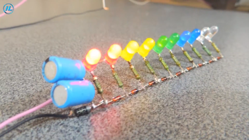
The build relies on a very simple circuit that relies entirely on analog electronics in lieu of the usual digital signal analysis usually employed for the job. It’s a barebones design that’s assembled using a jig to create the attractive circuit sculpture structure. It uses simple colored LEDs, assembled in a line with red at the bottom, stepping through yellow and green, to blue and white at the top. A series of diodes is placed in series, with the sound level having to exceed the voltage drop of successive diodes to light the higher LEDs. It’s intended to be directly connected to a speaker’s audio input, and thus likely does load down the amplifier output slightly.
The result is an attractive rainbow VU meter display that would look great as a part of any old-school stereo setup. We can imagine it would look even better if it was cast in clear resin. Video after the break.


Would the scaling change with volume level? Good encouragement to turn it up to 11 if so.
In the video he says he basically put the left channel to the device and the right channel to the LEDs, so yes it would.
To this right, you’d need to get the line level signal before the amplifier and boost it, as (and I’m open on correction on this) line level is only 2v peak to peak.
It should be noted that some stereo systems will output high voltages on the speaker terminals, with some more powerful systems in excess of more than 100V! It goes without saying that this could result in a painful, if not dangerous electric shock if you are not careful, and may even result in blown capacitors/diodes/LEDS or other components. This is especially applicable to older, more powerful HI-FI equipment that does not use the more modern switching-type amplification strategies like class D. Caution is advised!
100 Volts into 8 Ohms… that’s 1.25 kiloWatts.
Not your home stereos.
Unless you’re talking about ancient 300 Ohm systems, which would explain the high voltage.
Say you disconnected the speaker to test this thing. That 8 ohms is no longer connected to the output! Car audio amplifiers of 1000W are commonplace. Some amplifiers will trip out because of the open circuit, some will not. The math is easy enough. That being said, most standard audio gear has rail voltages of around 50-75V. Keep in mind this is usually positive and negative supplies, so the total voltage that can develop across the output will be higher than that. A lot of Pro sound gear, and some higher end stuff regularly has 100V rails, again positive and negative supplies. Obviously this isn’t because they always output that voltage, but because it gives them headroom and more dynamic range. I stand by my assertion that caution is advised! All it takes is a momentary open circuit during some louder music passage to see dangerous voltage on the speaker output terminals. That being said, it is kind of a neat idea, maybe not the best, but it does look cool. Just be careful if you plan to build one!
Audio amplifiers are voltage-output devices, meaning that the output voltage is not affected by the load connected, or lack thereof. The output signal voltage is unchanged with the output open.
Your statement of positive and negative rail voltage levels is correct, but you must also analyze your own statement, implying that there’s a reference those voltages are measured from. That reference is used as audio and circuit ground. That implies, and it’s true, that you will always get less voltage output than either rail can provide, none of one rail supply can ever add to the other. So as you said, 50-75 volts maximum.
It is indeed useful to add a disclaimer of caution when working with higher voltages, but it’s also highly unlikely this project would be used in such setups.
Car audio amplifiers that put out a hundred volts are not commonplace. That’s why the voice coils have even lower impedance at 4 Ohms and below.
My vintage radio has 800 ohm speakers such that the tubes can drive them directly without the need for a transformer. Those are older than the dinosaurs and impossible to replace, though my guess would be that they’ll die long after me so not my problem
I mean 1.25kW is not hard to believe. A lot of us diyaudio guys use pro-audio amps. For example I have a Behringer EP1500, bridged mono it’ll put out 1400W into a 4 ohm load. That’s about 75Vrms. https://www.behringer.com/product.html?modelCode=P0195
I personally use it for a subwoofer, but there’s no reason it cannot be used full range. Anyways there are absolutely amplifiers out there that can output in excess of 100Vrms.
I have a home stereo that uses 240 volts a cross the output section, it’s only rated at 500 watts into 8 ohms. So yes high voltage can be present at the speakers. To get distortion free audio takes higher voltages than a simple DC calculation would suggest.
If you’re an instructional video, then where’s your polarity?
Polarity?
Uh, we ain’t got no polarity.
We don’t need no stinking Polarity!
Lovely project 💡 VU meters are way cool
Love the tip on that guy’s soldering iron lol
Can you suggest some pre-amp IC for this UV meter to make it 200mV line-out-pluggable?
You can get a bar gragh led driver chip that works at preamp levels and forget the amplifier. It will be safer for your audio system.
Correct me if I’m wrong but that looks like a very flawed design to me. The bottom LEDs will get way too high currents when the level is high enough to turn on the top LEDs. Didn’t watch the (long) video to check if he talks about this.
just brainstormed with a simulator: you may put the diode ladder on one side, a resistor ladder on the other side, and the LED between them. Connect the voltage diagonal, so the current through the lowest LED passes all the resistors and the current through the highest LED passes all the diodes. Some tweaking of the resistor values is required, but then you can archive a quite constant current through the lower LEDs when the voltage rises (didn’t watch the video either, just the picture in this article)
You can use an LM-3915 to get a logarithmic response characteristic of a VU meter. Of course that is a change to active electronics, and you may need a power supply. There are lot of LM-3915 projects available on the web. You could weight the resistor/diode ladder of the circuit art approach, but the chip approach offers more options to tailor the display attack, decay, peak hold, etc.
There are probably counterfeit LM-3915 chips floating around, so knowing the reliability of the seller is advisable.