
In this USB-C series, we’ve covered quite a bit of USB-C – things that are well known, things that should be better known, and a couple things that just appeared online for the first time. We’ve covered almost everything in some depth except USB Power Delivery. I’ve described the process a bit in the “Power” article, but that was mostly about how to use PD by simply buying the right solution. However, that’s not enough for a hacker. Let’s see if we can make our own PD trigger board.
PD Trigger Board In 100 Lines Of Python
We’ll start with no pre-existing software stack – we’ll take a PD PHY (physical layer interface) chip, connect it over I2C, toggle its registers ourselves, and do our own packet crafting. I will use MicroPython, because I find it works best for educational purposes; plus, I genuinely like writing Python for hardware tinkering purposes, and I hope you can appreciate the benefits as well.
Our target for today? Getting 9 V voltage out of a USB-C PSU, short and sweet; basically, what every single trigger board out there is built to do. After we reach this target, you’ll be able to create your own trigger boards – but way cooler, customizable, with price likely comparable to a trigger board chip; plus, in Python, no less! Oh, and it will take us under a hundred lines of Python code to get there.
Minimum Hardware Requirements
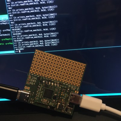
If you want to follow along, you’ll want the FUSB302 chip, and some kind of MicroPython board. I’m using a RP2040+FUSB302B combination on a devboard of my own design, but an ESP8266 would do just as well. FUSB302B is the new and seemingly functionally identical option – not sure what the differences are, and I’m pretty sure they won’t matter to us.
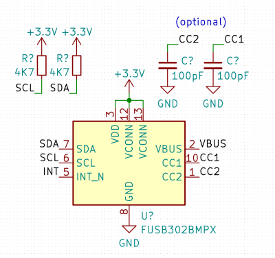 Of course, the FUSB302’s CC pins have to be connected to a USB-C receptacle; VCONN doesn’t matter to us here but you can short it to 3.3 V input. However, I do expect you to have a USB-C cable and a PSU with a USB-C socket, too – or a captive cable PSU, the captive/socketed part doesn’t matter much. And make sure your PSU is actually capable of voltages over 5 V – if it doesn’t state any, then it might not speak digital PD at all, only relying on analog signalling. 100 pF – 470 pF capacitors from CC to ground are desired, but by no means required. Wire up your 3.3 V, attach SDA and SCL (INT won’t hurt but isn’t needed for now), make sure I2C pullups are there, and let’s go!
Niceties? It’d be nice if you could attach an LED to VBUS; having a 1 kΩ resistor in series ought to be enough for even 20 V on VBUS. I imagine some LEDs might get unhappy at 17 mA, but most should survive just fine; if they don’t, replace the LED and double the resistor. This will be useful during debugging later on! You don’t have to connect the USB-C port’s VBUS to the FUSB’s VBUS, though, it might help later on if building a more proper device is your aim. Absolutely do make VBUS accessible so that you can probe it with a multimeter and check whether your code has run successfully!
Software Setup
For a start, download the FUSB302 datasheet, as well as the USB PD specification, version 3.0 – we will refer to them both. Having both of them open while playing with PD is highly advised, in fact! That said, for this installment, we will only need the FUSB302 datasheet.
 Get MicroPython onto your board, and initialize the I2C bus – here’s example code for RP2040, ESP8266 or ESP32. I highly recommend that you test the configuration and connections out in the MicroPython REPL first, through a serial terminal. Does an address like
 0x22 appear when you do i2c.scan()? Then you’ve wired everything up correctly! Does it not appear, or does the initialization fail? Make sure that your pins are defined properly, and you have pullups on I2C pins.
When an I2C device appears, you can play around. Try and read the 0x01 version and revision register. In general, consult the FUSB302 register map – it starts at datasheet page 18, and you’ll be jumping around these pages for a bit as you play!
Reminder on how to read and write registers of an I2C device in MicroPython:
# Writing 0xAA and 0x55 to address 0x22, register 0x3e
i2c.writeto_mem(0x22, 0x3e, bytes([0xAA, 0x55]))
# Reading one byte from address 0x22, register 0x43
data = i2c.readfrom_mem(0x22, 0x43, l)
# type of 'data' will be 'bytes', convert as needed, or just print it
Ready to proceed? Let’s switch away from REPL at this point – instead, I suggest you put code into a main.py document, transfer it to the board, then run it whenever you need to test it. My workflow for this mode is running a tmux session split into separate tabs for a terminal-based code editor and for a serial terminal/code upload shell – for code upload, I use ampy. If you’re looking for something GUI-based, I’ve had friends successfully use uPyCraft.
If you’re following this tutorial from CircuitPython, first, that’s admirable and I hope it’s easy enough for you to adapt the examples, and second, you have an advantage – it will be easier for you to upload your code, since CircuitPython supports storage device mode on things like the RP2040. However, there’s a disadvantage too – you’ll have to put more effort into debugging, since CircuitPython doesn’t let you introspect your code in REPL after it crashes – at least, it didn’t let me do it last time I tried, and that seemed to be a fundamental limitation.
Setting The Chip Up
First, we need to set a few registers in the FUSB302. These settings assume that a USB-C cable is plugged in; at least, most of them operate under such an assumption. I could set you up with a more sophisticated setup, but that’s not what this article is for – today, we’re getting a higher voltage out of a PSU we have connected, and we don’t need much for that.
First, a good practice is to reset the FUSB302 – who knows if your MCU has just been rebooted. Write 0x01 to 0x0c (RESET) register for that. 0x02 will reset the PD logic – we’ll need that later. Then, we need to get the chip’s different parts out of sleep – writing 0x0f to 0x0b (POWER) register will do. Write 0x00 to 0x06 (CONTROL0) to unmask all interrupts, then 0x07 to CONTROL3 to enable packet retries. Now, we’re ready to determine the CC polarity!
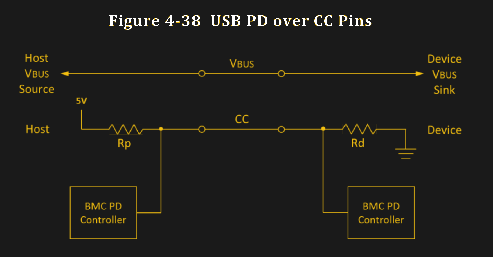
The FUSB302 has pulldown resistors implemented by default, and while we could detach them, they do help, as we’re working with a PSU right now – which has a pullup on the CC line. The PD communication only happens on one of the CC pins, and by measuring which one of them has a source pullup attached, we can determine which pin is connected to the PSU. The specific way to do this, I’ve borrowed from the Pinecil’s FUSB302 initialization code, through snooping upon it a logic analyzer. However, I’ve seen this exact method done in other FUSB302-aimed libraries as well.
This could very well be a cargo cult measure, given that one could theoretically use the port role automatic toggle (see CONTROL2) feature of the FUSB302 – I didn’t get that one to work well for me, however. Until now – the Pinecil implementation that I learned from, happens to be sink-only, and uses a manual measurement method. It’s straightforward – connect to CC1, measure the voltage, connect to CC2, measure the voltage, then compare. The FUSB302 has two convenient bits that convert CC pullup voltage to USB current levels allowed, and we can just compare those two bits between two reads.
First, write 0x07 (0b111) to 0x02 (SWITCH0), connecting the internal ADC to CC1 – then, read 0x40 (STATUS0), and get the bits 1-0 from that; those bits represent current levels, and the non-connected pin will indicate zero. Then, switch the ADC to CC2 by writing 0x0b (0b1011) to SWITCH0, and read STATUS0 again. If the CC1 value is larger than CC2, then the PSU is connected to CC1, and vice-versa. If both the CC1 and CC2 reading are at zero, then there’s no PSU detected – that’s where you add a “nothing detected” special case to your code, and then perhaps wait for a PSU to be attached. Alternatively, as a homework assignment, you can try and get the toggle feature working!
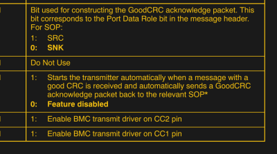
Starting The Transmitter Has Consequences
We now know the CC pin to operate on – let’s make use of that. Say, our pin is CC1. We enable both the receive and transmitter on it, as well as automatic GoodCRC responses. Write 0x25 (0b100101) to 0x03 (SWITCH1) register – bits 0-1 will change depending on which CC pin you want the transmitter to connect to, bit 2 enables automatic GoodCRC responses, and bits 5-6 say that we’re going to talk PD revision 2.0. We’re actually going to be talking PD 3.0, but the FUSB302 datasheet hasn’t been updated to say that it’s outright supported, even though it seems to be fully functionally compatible as far as I’ve been told. Then, write 0x07 to the SWITCH0 register – connecting the measure block to the CC1 pin, just like when we were measuring it.
The GoodCRC part is a “point of no return” of sorts. The GoodCRC message transmission means that, whether you’re talking to a PSU or a device, the other side essentially receives ‘message acknowledged’ responses to whatever they sent. In short, sending GoodCRC responses is a sign of intelligent life sent to the device on the other side of the USB-C cable. Some USB-C messages, however, also require an intelligent response within a certain timeframe after they’ve been received – if you send a GoodCRC response automatically, but then don’t send a response expected, that might incur a ‘something went wrong’ response on the other end.
 For instance, a USB-C power supply will automatically send out a list of its capabilities – power profiles, the options we know as “5 V @ 3 A”, “12 V @ 2.25 A” and so on. If you acknowledge those with your automatic GoodCRC response, you have 500 ms to reply with the power profile you want to use – even if you plan to stay at 5 V. The USB-C specification requires a PSU to disable and enable VBUS if it doesn’t receive a profile response – most PSUs obey this. If you send GoodCRC to the advertisement but don’t reply with a preferred profile, and your device is powered from USB-C VBUS, the PSU will cause it to go into an infinite power looping. The solution is simple – reply as soon as you get an advertisement; if you want to ask for a different profile later, you can always do so!
Nevertheless, we should do a bit of cleanup before we start receiving messages. Write 0x40 into 0x06 (CTRL0) to flush the TX buffer, 0x04 into 0x07 to flush the RX buffer, and 0x02 into 0x0c (RESET) to reset the FUSB’s internal PD logic.
Now we’re all set – the messages will be coming into the FUSB302’s receive buffer, and we’ll be able to read them.
Getting Messages
A PD PSU will automatically send out a message with its capabilities, and it will try to do that a few times after power-up – until the moment that a message is acknowledged with our GoodCRC. As your board is presumably not powered from the same USB-C port, you will be able to receive the message from inside the REPL and poke at it – however, do remember that the PSU will timeout unless you’re able to request a profile on time, and you won’t be able to do that interactively; in other words, you need to craft a response automatically. Nevertheless, we will be able to do just that fairly easily!
How do you check whether there’s something in the receive buffer? Read the 0x41 (STATUS1) register and check the bits 5-4: bit 5 will be set to zero when the receive buffer contains something. Then, you can read bytes out of the buffer – with a block read, from the 0x43 address. The buffer might contain multiple messages at once, however, in a simple USB-C PD power supply scenario, you can expect there to be one message.
You don’t have to carefully read a single message’s worth of bytes for now – for ‘checking that things work’ purposes, you can just read the entire buffer, which is 80 bytes long. Let’s do just that!
>>> b = i2c.readfrom_mem(0x22, 0x43, 80)
>>> b
b'\xe0\xa1a,\x91\x01\x08,\xd1\x02\x00\x13\xc1\x03\x00\xdc\xb0\x04\x00\xa5@\x06\x00<!\xdc\xc0H\xc6\xe7\xc6\x00\x00\x00\x00\x00\x00\x00\x00\x00\x00\x00\x00\x00\x00\x00\x00\x00\x00\x00\x00\x00\x00\x00\x00\x00\x00\x00\x00\x00\x00\x00\x00\x00\x00\x00\x00\x00\x00\x00\x00\x00\x00\x00\x00\x00\x00\x00\x00\x00'
We Got Contact!
We received our first message! And we only needed to follow a relatively simple initialization sequence – this is not all that much harder than playing with a HD44780 LCD; and you could surely stuff this code into an ATTiny, even. I’d like to thank [Ralim] and [Clara Hobbs] for laying the groundwork; the commands I’m describing, are theirs to have figured out – I couldn’t figure out the full sequence by myself, so, a lot of the “which commands are actually needed for it to work” was taken from their stacks.
In the next article, we will parse this message and craft a proper reply to it! I have to apologize for leaving you on a cliffhanger, but properly walking you through parsing messages will take a bit of time. However, you don’t need to do any FUSB302 configuration anymore – you are already prepared to reply with a PD message, as soon as you can craft a suitable reply. Do you feel impatient? Want to do it yourself, as homework? Here’s my code for parsing such messages, here’s IronOS code responsible for the same, and here’s my pretty-printed I2C communications capture of a Pinecil negotiating a higher voltage profile. Otherwise, we’ll finish this next week!


If you want a pretty print-out of PD messages, use the PD decoder in sigrok/Pulseview.
It is going to look somewhat like this:
https://community.element14.com/technologies/power-management/b/blog/posts/usb-pd—cc-decoding-adventures
Also information, on how to ready CC signals with a 3.3V logic analyzer.
the entire fun of USB-C is how much you can do with it, how simply you can make USB-C stuff, and how much there’s to hack on! I’ve been using barrel jacks for decades, you just gotta trust me that they’re not all that great 😝
Barrel jacks were the best before PD. But they had no negotiation. You needed different adapters for different voltages, or manual switch settings that could easily get messed up accidentally. Way too much trouble when it can be avoided with USBC so easily. The user experience is just so much better.
Lack of negotiation is in many ways a feature though – the renegotiation done for every plugged in device when a new device is connected seems to be a 100% certainty to brown out every device sharing that hub in my experience so far. And the ‘dumb’ supply just works if it provides the voltage the device has stamped on the bottom – something you can’t be sure of in USB-C PD stuff as the device can be wanting something the supply won’t give yet both are actually correct to some optional set of the specs…
IFF PD was actually reliable, universal and strict standard where every cable just works rather than a constant but entirely hidden problem I could see calling the user experience better, but as it stands it is at least as much trouble as it is help…
I’ve noticed that, power adapters seem to brown out a lot, but it’s not a super big issue most of the time, since USB is usually used with things that have internal batteries.
Could be an issue if you accidentally reboot your router while adding a new device to the adapter it’s on, but usually that will just mean waiting a few minutes, while barrel jack devices can send you on 20 minute searches of the whole house for an adapter with the obscure voltage they use.
Plus, dumb supply devices can be completely destroyed by incorrect connections. I’ve seen 12v devices destroyed because someone connected 120vac, albeit that was a wire pigtail diy connection type thing, and the people who set it up didn’t have any documentation and guessed I think.
That’s odd. My USBC adapters never brown out. My non negotiating USB A adapter does if you plug too much into it. That’s on the engineers for not knowing their capacity or how to respond to their source supply.
So much stuff though the USB-C PD hub won’t have batteries – as the stuff you are using that powered hub to connect to your computer generally doesn’t have batteries. The hub is required because devices don’t come with A ports anymore, or enough ports and you can’t keep the computer plugged in somewhere else either…
For me it has been a big pain as when you are playing with liveboot off a USB stick that must be on a USB hub as the device hasn’t got an USB-A port, or even enough USB sockets to have power and devices connected. So every time you have to plug anything else into the hub – like perhaps another USB stick, or the keyboard – even dumb 5V only devices, the boot disk and everything else on the hub browns out and its fairly likely the system won’t recover, and some HID devices seem to go very wonky as well…
You should check if it’s a faulty/misdesigned hub on your part, or perhaps a subpar PSU. Nothing about USB-C requires this – in fact, 5V-output-only USB-C hubs (aka, the overwhelming majority of them) work just the same as the old USB-A-equipped hubs. In fact, this is a seriously bizarre thing to encounter!
Oh and Carl if you go plugging in 3A worth of load to a 1A supply or a 65W required load into the 20w USB-PD supply it won’t work with USB-C either… That isn’t on the engineers it is on you (unless the adapter supplied can’t actually power JUST the device it came with).
I’m 90% sure it is happening as it is sort of required by the spec, in the sense the spec requires a renegotiation if the power demand changes, so plug anything in at all it notices and refreshes affecting every connected device, during which process power is interrupted for just long enough to bork. And this hub must do the over 5V PD for the power passthrough back to the computer at least while at the same time as being a hub.
I don’t have a huge amount of USB-C stuff but it doesn’t matter which PSU or HUB and none of them are cheap crummy imports you would half expect odd behaviour from. And with the exorbitant cost of ‘brand’ USB-C stuff I’m not spending another 6 months worth of project money hunting for the one that actually works properly, assuming such a thing actually exists, which every search seems to suggest it doesn’t as all you ever find is more horror story…
I agree barrel jacks are underrated and underused in stationary devices today. But a USB-C compliant 5v3A system is 3 part bom costing less than a dollar, and gives you an infinite amount of compatible power plugs and adapters.
Looking forward to more and cheaper Arduino modules that have the USB-PD chip built in, so many possibilities! Especially with PPS, pretty much anything can be retrofitted.
If PPS ever becomes more popular :'(
I think PPS sounds extremely useful but it’s just rare and expensive so far
Oh, I bought a few cheap USB-C PSUs as I’ve been shifting to USB-C, and without even trying to get there, turns out that half of them have at least 3V-11V PPS! My laptop’s (Framework) native charger also turns out to have PPS, even though it’s not advertised on the label – full 3V-21V range, even. So, definitely not rare – you will be limited to 3V-11V PPS with <45W PSUs, but, PPS is out there and you can find some if you look for it.
I have retrofitted my portable cpap to usb c but not every supply provides the 15v profile it needs so i am debating designing a device that tries to get 15, but if that fails then gets 9,12,or 20 and buck/boosts to 15v so I can use almost any supply.
15V should be a standard USB-PD value. If it can’t get to that, it almost certainly can’t do 20, and 12V may not be available either. So, you’re either looking at 9V @ 3A at most, or just not working. 12V isn’t part of the spec anymore, but a number of supplies still provide it. Also, PPS allows the device to ask for 12V as well, as it can ask for any voltage in the range supported by the charger (specifically for letting phones just route the voltage almost directly to the battery, instead of having to convert the voltage again to what the battery actually wants.
Yep, this is exactly the kind of thing possible! As CmdrKien says, having 20V basically requires 15V by the standard, which PSUs obey – however, there’s plenty of PSUs that aren’t powerful enough and hence aren’t required to do 15V. One thing tho – how many amps do you need, and what’s the resulting wattage? See if the PSUs you’re aiming for, can even provide the power you’re looking for – if not, you might want to stick with beefier PSUs. The 15V-less supplies I have here, are around 18W or such – if 18W isn’t enough for your CPAP, then that won’t work.
Provided ~15W of power is OK, what I’m thinking will work for you – a trigger board set for 15V, and a microcontroller with a FET, plus, the boost with its own FET control, I gather. When the trigger board wakes up, the MCU wakes up, waits a bit, and uses an ADC to measure which voltage is negotiated – if it’s 15V, it is let straight through by opening one FET, and if it’s less than that, then the boost path is enabled by turning different FETs on instead. Feel free to join the HaD Discord and @ me for any questions!
The 302B is the controller I’ve been using with my Attiny for years. Beware some of it’s cousins are total crap. One of the features I like most is it can read SOP’ messages as well. I use mine with the MCU internal pull up. Not the recommended 4.7k but I’m not running the thing at 1MHz either…
The 302B has a few versions that simply have different i2c addresses as well. Oddly are about 30% more expensive.
uPyCraft is broken the never ending missing SourceCodePro.ttf font. Try Thonny instead.
Hello,
I see that you are using a chip to do the PD to “digital” conversion. Is it not possible to just use 2 digital pins and do it 100% in software?
The bit banging with the 5 bit per nibble does not seem too complex…
Thanks from a guy trying to add PD to a basic arduino board at no HW cost (except for the pull down).
Cyrille
I’m sure you could. Just depends on how much free time you have to dedicate to it. I’d chip in sometime for an open source driver. Personally I use the fusb302b. But it can’t do SOP’ without doing SOP…
See https://www.reclaimerlabs.com/blog/2017/2/1/usb-c-for-engineers-part-3
Hello,
How much does a fusb302b cost (for information)?
I am working on an arduino powered board that drives nema17 (think CNC control, but in my case I control a telescop mount)…
I would like to get rid of the separate power supply and just use USB C as it would make thing simpler (cables around a telescope at night are not good)…
But I wanted to do it with minimum HW changes/work and adding a whole extra chip did not seem like such a simple solution.
Thanks
Cyrille
Thank you very much for writing this article, it helped me more than you could imagine.
I have written my USB-C PD code in C, and I have noticed some instability issues regarding finding the correct CC-line to communicate with. https://hackaday.com/2023/02/14/all-about-usb-c-talking-low-level-pd/#comments
In your code you call the function find_cc once more after the while loop, in my case the communication is more stable if the last call is removed.
Once again, thank you very much for the inspiration and I have learned a ton by reading this and the PD 3.1 standard!
I meant to add this link: https://github.com/CRImier/AltmodeFriend/blob/1fa44c282e6d5b7796f51fc36662d464c36e99c6/pdstacc.py#L80-L91
Vielen Dank für diesen Artikel! Ich habe durch diesen Artikel sehr viel dazugelernt! Inzwischen gibt es den Controller RAA489400 von Renesas. Dieser PD 3.1 Controller kann auch EPR mit 28,36 und 48 Volt bis 240 Watt.