
Back in the 18th century, clockmakers were held in high esteem, as turning pieces of metal and wire into working timepieces must have seemed like magic at the time. The advent of mass production made their profession largely obsolete, but today there are several hardware hackers whom you could consider modern heirs of the craft. [Hans Andersson] is one of them, and has made a name for himself with an impressive portfolio of electromechanical clocks. His latest work, called the Time Slider, is every bit as captivating as his previous work.
 The mechanical display is almost entirely made of 3D printed components. Four flat pieces of red PLA form a basic 88:88 indicator, onto which the correct time is displayed by sliding frames that black out certain pixels. Those frames are moved up and down by a rack-and-pinion system driven by stepper motors. Evertyhing is controlled by an Arduino Mega, acoompanied by a DS3231 RTC and eight ULN2003-based stepper motor drivers.
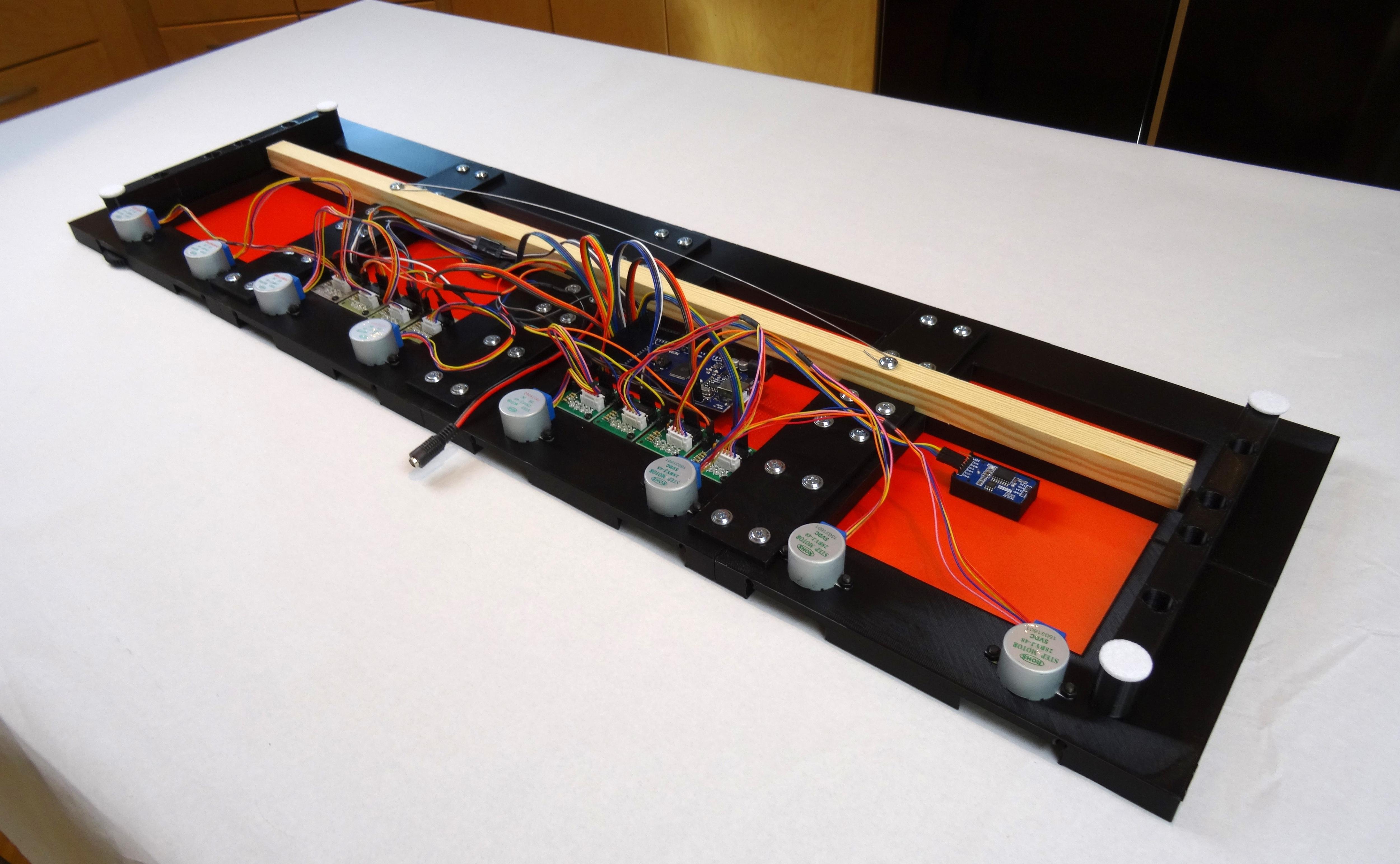
[Hans] wrote a detailed assembly guide to go along with the STL files and Arduino code, so it should be easy make your own Time Slider if you have a decent supply of PLA filament. The display takes about ten seconds to update, but the process has certain hypnotic quality to it, helped by the mechanical whirring of the stepper motors in the background. Especially the hourly change of three or four digits at once is mesmerizing, as you can see in the video embedded below.
Time Slider is the latest in [Hans]’s long line of mechanical clocks, which includes the Time Twister series that evolved from a clever Lego-based design to a neat 3D-printed model. The rack-and-pinion system can also be used to make a compact linear clock.


beautiful
My favorite HAD featured clock to date. There’s something soothing about the smooth action.
Then….I turned on the sound….the irritating noise of the mechanism destroys the effect. 👎
Read the replies below the instructable article, apparently he has overdone the audio in the video a bit.
Well done! The accurate registration of the masks is impressive. (Also you can tell that the author doesn’t have cats – those would be an irresistible temptation).
Where’s the gif?
Nice, if it weren’t for the noise
Yeah, the grinding sound….. but that is because of the geared steppers being used.
A bit annoying, but can be reduced lot by placing soft dampening materials and weights here and there in the structure, which probably resonates a lot. I would also use silent blocs to fix motors. Once the structure becomes heavier, it won’t easily resonate at these frequencies, lowering considerably that noise level.
The masking pieces are far from optimal, I noticed them moving between every digit even when that column doesn’t change. The one on the far right for example has 13 empty squares in a row for a digit with only 5 squares per column. Is that just supposed to be for effect?
It is optimal, but it’s optimized for the amount of actuators (cost and complexity)
There are only 2 motors per digit, the right 2 columns are actually only one column, so the right column moves along as the middle column needs to change
Beautiful, but god it is loud. Are these motors from an eastern European elevator?
Yes