At Hackaday, it is always clock time, and clock time is a great time to check in with [shiura], whose 3D Printed Perpetual Calendar Clock is now at Version 2. A 3D printed calendar clock, well, no big deal, right? Grab a few steppers, slap in an ESP32 to connect to a time server, and you’re good. That’s where most of us would probably go, but most of us aren’t [shiura], who has some real mechanical chops.
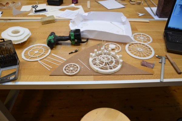
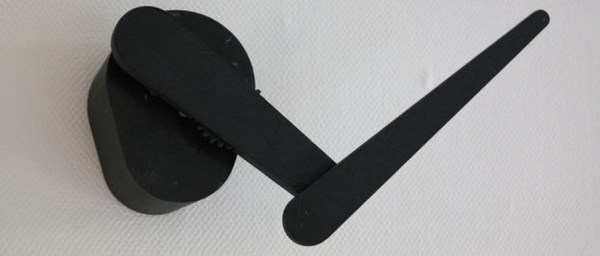
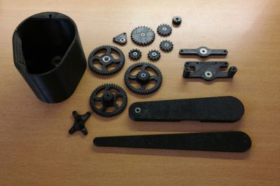
This clock isn’t all mechanical. It probably could be, but at its core it uses a commercial quartz movement — you know, the cheap ones that take a single double-A battery. The only restriction is that the length of the hour axis must be twelve millimeters or more. Aside from that, a few self-tapping screws and an M8 nut, everything else is fully 3D printed.
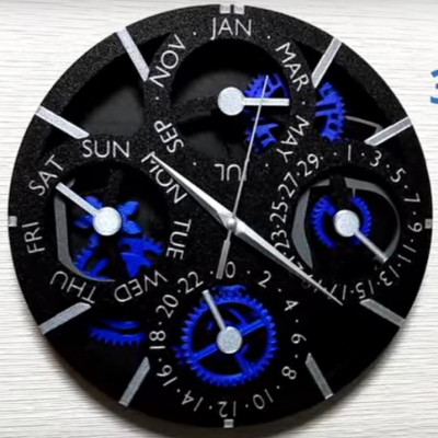
From that simple quartz movement, [shiura]’s clock tracks not only the day of the week, the month and date — even in Febuary, and even compensating for leap years. Except for the inevitable drift (and battery changes) you should not have to adjust this clock until March 2100, assuming both you and the 3D printed mechanism live that long. Version one actually did all this, too, but somehow we missed it; version two has some improvements to aesthetics and usability. Take a tour of the mechanism in the video after the break.
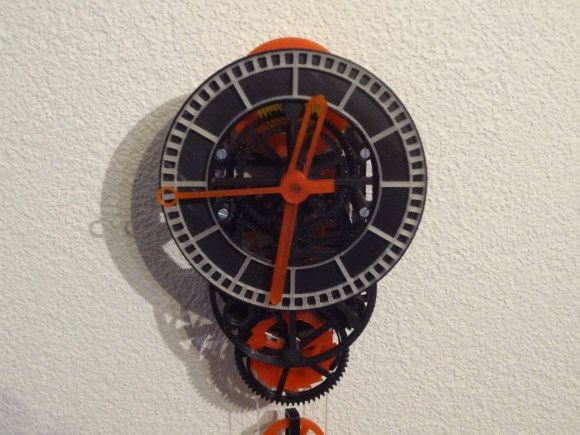
We’ve featured several of [shiura]’s innovative clocks before, from a hybrid mechanical-analog display, to a splitless flip-clock, and a fully analog hollow face clock. Of course [shiura] is hardly our only clock-making contributor, because it it always clock time at Hackaday. Continue reading “Printed Perpetual Calendar Clock Contains Clever Cams”
 The 3D printed parts were designed by [dragonator] himself. All of the design files are available
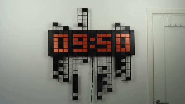
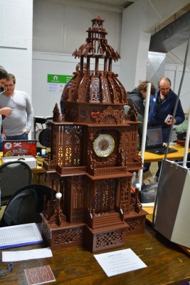 As you might imagine, a great deal of work went into this build, beginning with the scanning. [Jason] starting scanning last October and finished in January. Printing started January 9th, and he told me the final pieces were printed early this morning. We know you want all the details, so here goes: this build took just over six rolls of PLA at 20% infill. It’s 48″ tall and about 24″ wide. It was printed on what [Jason] referred to as his “very modified” Replicator 2. He glued the pieces together with Testor’s, and that took about 30 hours. All through the project, he kept meticulous notes in a spreadsheet of print times and filament used.