If there’s one thing we’ve learned from [Chris] at Clickspring, it’s that a clockmaker will stop at nothing to make a clock not only work perfectly, but look good doing it. That includes measures as extreme as this complete re-toothing of a wheel from a clock. Is re-toothing even a word?
The obsessive horologist in this case is [Tommy Jobson], who came across a clock that suffered a catastrophic injury: a sudden release of energy from the fusee, the cone-shaped pulley that adjusts for the uneven torque created by the clock’s mainspring. The mishap briefly turned the movement into a lathe that cut the tops off all the teeth on the main wheel.
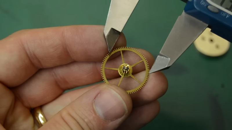
Rather than fabricate a completely new wheel, [Tommy] chose to rework the damaged one. After building a special arbor to hold the wheel, he turned it down on the lathe, leaving just the crossings and a narrow rim. A replacement blank was fabricated from brass and soldered to the toothless wheel, turned to size, and given a new set of teeth using one of the oddest lathe setups we’ve ever seen. Once polished and primped, the repair is only barely visible.
Honestly, the repaired wheel looks brand new to us, and the process of getting it to that state was fascinating to watch. If the video below whets your appetite for clockmaking, have we got a treat for you.


Respect.
Amazing work – clearly he’s well setup for these task but the design and use of that jig was very inspiring even for hacks like myself that work on substantially, well, more substantial parts.
My explanation to people is that if turning the cranks is being a “machinist”, I could train a monkey to be a “machinist” (and I’m sure some are). The challenge is how do you fixture a part in ways that you can do as much as possible because once it’s in a fixture, you can typically easily hit parallel, concentric, perpendicular, etc. Once you take it out, how do you get back to your reference orientation?
That jig was the secret sauce to the process – well, that and some mad machining skills in general.
Nice work!
Not to take anything away from Tommy’s wonderful workmanship…. but I’m kind of ashamed to admit that I don’t see the problem with the original gear.
From the article title, I was expecting something a lot worse as well, like really bad.
It looks like the top of the teeth were damaged but the root portion was still there. I’m figuring it was probably enough to impact the functionality but it might have still sort of worked and just offended his sensibility.
Clearly he was in a position to address effectively either reason (or both).
Don’t stress :) When it comes to clocks and watches, the gearing difference between the mainspring barrel and the final wheel in the drive train is enormous, so once you’re looking at the last couple of wheels there is very little power there. When working on old verge watches (which have a heavy mainspring) from the 1700’s, all I need to do to really securely stop the train is put a little paper dart in the teeth of the second last wheel. A stray hair in the wrong place will have the same effect when trying to use it as your daily timekeeper.
So any deviation from perfection in the wheel train has large consequences on it’s running accuracy.
Hope this was helpful.
All the Best :)
Yeah, it’s not apparent at first glance (unless your really into clocks or a fine gear machinist).
Try pausing the video around the the 2:24 mark. You can see the teeth are not perfectly similar. Especially the two teeth just below the thinner bright light reflection line running a long the length of the cylinder. Some teeth are better than others, look at how straight the line is on the edge of the teeth. The less straight the line, the more wear that has occurred.
I also had to look very carefully to see the difference in before vs. after. The damage isn’t quite as described, from what I can see. In the before picture, some of the teeth, perhaps half a dozen on the left side at 1:38, appear to have been shaved down a tiny bit. Their tops are flatter instead of slightly more triangular. Other teeth appear to be fine (ie, looking the same as in the after image).
The odd lathe setup isn’t as weird as it looks. The lathe head is used as a dividing plate to index the part, and a cross slide mounted milling head is used to cut the tooth forms.
It is same as using a horizontally mounted rotary table on a mill.
The stuff that’s somewhat unusual about that lathe include flat belt drive and an overhead shaft that the lathe motor is driving via belt and is then driving the cross-slide secondary turning center. I also thought it was interesting that the compound slide has t-slots parallel to the lathe axis so you can mount the toolpost in multiple locations, or as he does, a Z axis that bears the live tooling.
I thought it was interesting that he has his headstock set up for both direct indexing and compound. I’ve added something similar onto mine, but it’s either/or, and it’s kinda cool he has a replaceable index plate on the spindle itself. I’d like to know how that compound indexer interfaces with the spindle.
I was kind of wondering about the long ~ 1/4″ wide drive belts (two of them) and the apparent wobble when driving the respective equipment. Seemed such a wobble would induce chatter and chatter defects into such a micro-sized object. Must not be as bad as it looked.
Amazing repair.
Wow, I’ve just found a new YouTube channel to watch, this guy is a real craftsman.
All those exposed belts, scary. When you are frustrated and tired it is easy to concentrate too much on the part and forget about the monster inches away.
You’re so awesome! I don’t believe I have read a single thing like that before. So great to find someone with some original thoughts on this topic. Really.. thank you for starting this up. This website is something that is needed on the internet, someone with a little originality!