One of the first things that an amateur radio operator is likely to do once receiving their license is grab a dual-band handheld and try to make contacts with a local repeater. After the initial contacts, though, many hams move on to more technically challenging aspects of the hobby. One of those being activating space-based repeaters instead of their terrestrial counterparts. [saveitforparts] takes a look at some more esoteric uses of these radio systems in his latest video.
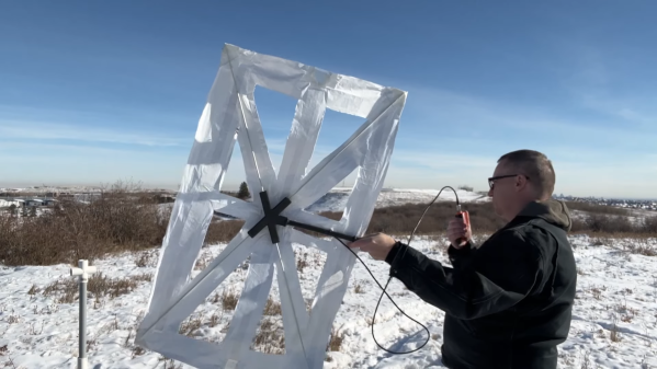
There are plenty of satellite repeaters flying around the world that are actually legal for hams to use, with most being in low-Earth orbit and making quick passes at predictable times. But there are others, generally operated by the world’s militaries, that are in higher geostationary orbits which allows them to serve a specific area continually. With a specialized three-dimensional Yagi-Uda antenna on loan, [saveitforparts] listens in on some of these signals. Some of it is presumably encrypted military activity, but there’s also some pirate radio and state propaganda stations.
There are a few other types of radio repeaters operating out in space as well, and not all of them are in geostationary orbit. Turning the antenna to the north, [saveitforparts] finds a few Russian satellites in an orbit specifically designed to provide polar regions with a similar radio service. These sometimes will overlap with terrestrial radio like TV or air traffic control and happily repeat them at brief intervals.
[saveitforparts] has plenty of videos looking at other satellite communications, including grabbing images from Russian weather satellites, using leftover junk to grab weather data from geostationary orbit, and accessing the Internet via satellite with 80s-era technology.