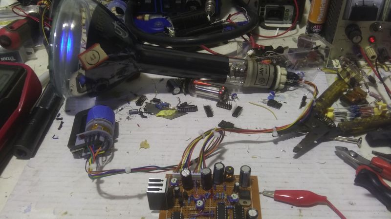
Real-time flight data used to be something that was only available to air traffic controllers, hunched over radar scopes in darkened rooms watching the comings and goings of flights as glowing phosphor traces on their screens. But that was then; now, flight tracking is as simple as pulling up a web page. But where’s the fun in that?
To bring some of that old-school feel to his flight tracking, [redacted] has been working on this ADS-B scope that uses a real radar CRT. As you can imagine, this project is pretty complex, starting with driving the 5FP7 CRT, a 5″ round-face tube with a long-persistence P7-type phosphor. The tube needs about 7 kV for the anode, which is delivered via a homebrew power supply complete with a custom flyback transformer. There’s also a lot going on with the X-Y deflection amps and beam intensity control.
The software side has a lot going on as well. ADS-B data comes from an SDR dongle using dump1090 running on a Raspberry Pi 3B. The latitude and longitude of each plane within range — about 5 nautical miles — is translated to vector coordinates, and as the “radar” sweeps past the location, a pip lights up on the scope. And no, you’re not seeing things if you see two colors in the video below; as [TubeTime] helpfully explains, P7 is a cascade phosphor that initially emits a bright-blue light with some UV in it, which then charges up a long-persistence green phosphor.
Even though multicolored icons and satellite imagery may be more useful for flight tracking, we really like the simple retro look [redacted] has managed to pull off here, not to mention the hackery needed to do it.


I like the idea, but it somehow looks way less good than I was expecting. Especially the sweeping line is *very* jittery.
The narration pretty well explains the source of the current limitations. I think it’s great for hackers to do this because it lets others better understand pitfalls. Posting a flawless project with no explanation is much less interesting.
I second this. A failure is only a failure if nothing can be learnt from it.
That’s why I respect those who admit their mistakes and talk about them.
That way, others can learn from it or better understand their own, similar mistakes.
I wonder if part of the problem is the rolling shutter effect from the camera, I’d be curious to see it at a very high fps like 240.
Reminds me of the days of 8s/7.2s Slow Scan TV..
RADAR indicators that used P7 phosphors generally used a yellow filter over them to eliminate the blue-white short-persistence component of the light the screen produces, which reduces operator fatigue.
Wondering if you could do something similar with an old digital storage scope and just feed it via the 2 channel inputs…..
Well, yeah, you could, but then you’re just plotting the data on a computer display, right?
Could you explain in more detail the process of driving the 5FP7 CRT and the components involved, such as the custom flyback transformer?