
Last time, we’ve looked over FET basics, details, nuances and caveats. Basics aren’t all there is to FETs, however – let’s go through real-world uses, in all their wonderful variety! I want to show you a bunch of cool circuits where a friendly FET, specifically a MOSFET, can help you – and, along the way, I’d also like to introduce you to a few FETs that I feel like you all could have a good long-term friendship with. If you don’t already know them, that is!
Driving Relays
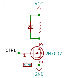 Perhaps, that’s the single most popular use for an NPN transistor – driving coils, like relays or solenoids. We are quite used to driving relays with BJTs, typically an NPN – but it doesn’t have to be a BJT, FETs often will do the job just as fine! Here’s an N-FET, used in the exact same configuration as a typical BJT is, except instead of a base current limiting resistor, we have a gate-source resistor – you can’t quite solder the BJT out and solder the FET in after you have designed the board, but it’s a pretty seamless replacement otherwise. The freewheel (back EMF protection) diode is still needed for when you switch the relay and the coil produces wacky voltages in protest, but hey, can’t have every single aspect be superior.
The reason you can drive it the same way is quite simple: in the usual NPN circuit, the relay is driven by a 3.3 V or a 5 V logic level GPIO, and for small signal FETs, that is well within Vgs. However, if your MCU has 1.8 V GPIOs and your FET’s Vgs doesn’t quite cut it, an NPN transistor is a more advantageous solution, since that one will work as long as you can source the whatever little current and the measly 0.7 V needed.
And here’s our first two friendly transistors, 2N7002 and BSS138 – they’re both small-signal N-FETs, fit for exactly this kind of job. The 2N7002 is a pretty classic part – you will see it a lot in whatever place an N-FET can fit. The BSS138 is very similar, with a tad higher Rds range, but a tad lower Vgs range – you’ll see it in some Sparkfun or Adafruit schematics. You can safely buy a bunch of either of these, and use them in your circuits whenever you need a small N-FET you can drive with a GPIO.
Level Shifting
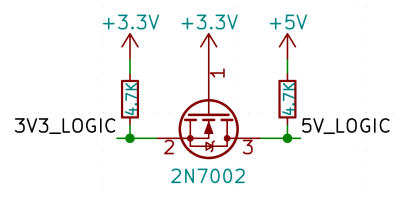 There’s more to small logic-level FETs, of course – for instance, if you ever needed to level-shift a few signals back and forth, you might’ve used those small ‘level shifter’ boards with four SOT23 parts on them. Those SOT23 parts are actually FETs, and our [Jenny List] has covered this kind of shifter in her extensive article about level shifting. This method is also cheap, simple, and will work with the overwhelming majority of the signals you’ll ever want to level-shift – all the more reasons to stock up on small signal N-FETs!
Reverse Polarity Protection
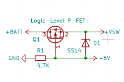
Here’s the ever-so-wonderful circuit that lets you do lossless reverse polarity protection with a FET! You can use either kind of FET – often, a P-FET is used for this, since having uninterrupted common ground has its benefits, but an N-FET will work too. This way of reverse polarity protection is way, way better than using a series diode, because you don’t waste anywhere near as much power – at 1-2A of power consumption, a diode can have you waste over 1W of power into heat.
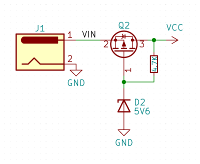 If Vgs isn’t higher than your expected power input, all you need to do is tie a P-FET’s gate to the negative pin, connect the power input to the positive pin, and have the drain pin be the output. Otherwise, if your input voltage might exceed Vgs or reverse Vgs thresholds, you’ll want to add a zener diode and a resistor to clamp the voltage. This kind of reverse polarity protection is cheap, lossless, and can absolutely save your components from a fiery death.
Of course, unless your circuit is quite low-power, you’ll want to move beyond small-signal FETs – what about the power input for a development board you’re working on? Perhaps, you could even use the same kind of FET you’d use for high-side switching peripherals? Let’s look into more powerful FETs – specifically, a few small yet good P-FETs that can handle higher currents without breaking a sweat.
There are quite a few small but powerful FETs with maximum Vgs range from 12V to 24V and maximum Ids around 2A-4A, that fit a large amount of occasions. Some of them have boast logic-level input, which usually means reasonable Rds at Vgs considerably lower than 3.3V logic high level, i.e. 1.8V – if you ever need to switch power to a 3.3V WiFi module and you want to do it with a GPIO, such a FET will fit the bill. Others don’t mark themselves as logic-level, but have reasonable Rds at low Vgs.
Out of my favourite all-purpose higher-current P-FETs, I’ve started out with IRLML6401 and IRLML6402, and now I use their Eastern counterparts, CJ2305 and HX2301A, purely because these are cheaper on LCSC. When it comes to N-FETs of similar caliber, IRLML2502 is great, and AO3400A has been an Eastern-made gadget classic for years. Looking for more? Check out this Ask Hackaday installment, where hackers gave us suggestions on exactly this kind of FETs.
Power Path
We’ve all seen a two-diode circuit, letting you power a circuit from either a DC power input or a battery with seamless switching. However, there’s a problem – while on battery power, having a series diode will have you lose out on a decent chunk of output voltage, and that is especially noticeable when powering a 3.3V circuit from a LiIon battery with its 4.2V-3V voltage range. This circuit takes the load off the battery while it’s charging, powering the load from 5V instead. While having the load perma-connected to the battery in parallel sounds like it could work, you don’t want to interfere with the charger’s CC/CV cycle.
 I’ve mentioned this one in the LiIon circuitry article, but it bears a highlight once again – it’s just that great of a circuit to have. Of course, you’ll want a FET that fits the bill, and logic-level P-FETs fit this circuit wonderfully. Oh, and sizing the resistor correctly can help with issues – you can safely go for something like 10 kΩ or even 47 kΩ, but if your circuit brownouts when disconnecting the charger, you can lower it down to as low as 1 kΩ; a FET gate doesn’t need all that much current to stay charged, after all.
Keep in mind – compared to the usual high-side switching arrangement, this circuit turns the FET around, swapping drain and source so that 5V doesn’t feed into the battery through the body diode. it will work nevertheless, specifically because the body diode results in voltage on the source pin, but keep in mind that the Vgs threshold has to be calculated by subtracting the body diode drop from the lowest possible battery voltage – the FET might not open otherwise.
Soft Start
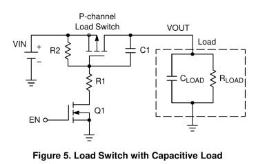 Sometimes, when you switch power to a peripheral like a GSM modem on its own breakout board, with some hefty capacitors on its power rail, it’s going to consume a whole lot of current and dip the voltage – likely, having your microcontroller brownout and reboot. With a single capacitor between gate and drain, you can add primitive soft-start to your high-side-switching P-FET-based circuit – having the FET spend longer time in its linear region as it is being switched on, pre-charging the capacitors before it fully opens, and smoothing out the power draw peak. This is a hack, but it solves the issue, and it’s something you can even bodge in post-production.
Would you like to know more? Here’s a wonderful appnote from onsemi, talking about basics of load switching with FETs, going into both practical examples of it and the math behind it, as well as cases where you might want to use a load switch instead. Oh, and what would those be, by the way?
When A Load Switch Fits Better
It’s hard to match just how well-integrated ICs can be – a single chip can solve all of your problems in a way that a discrete-component solution might never be able to. For instance, let’s say you want to switch a 5V/1.5A load, but you’d also quite benefit from overcurrent protection. With a self-built FET-based load switching solution, you will need to add a current-measuring resistor and an opamp or a comparator, at the very least. On the other hand, a load switch like a SY6280 has all of the features that you could have when building your own high-side switch with FETs, a current limit easily configurable with a single resistor, and even an optional output discharge resistor in case your device could benefit from not having residual voltage after you switch it off.
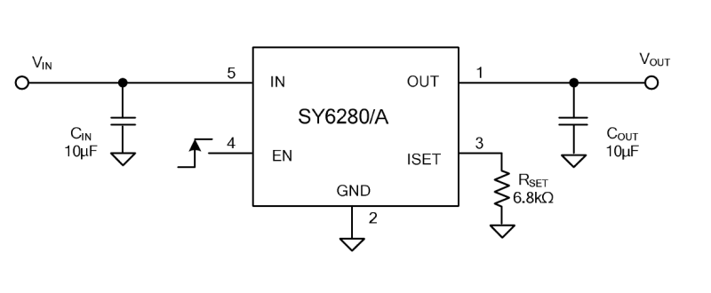 All in all, there’s a large variety of load switches designed to make your circuits less complex and more capable, and they’re not all that much more costly than having an extra FET. They all have FETs inside of them, but they’re GPIO-controllable as a rule – no more need for minding gate capacitance or Vgs. Some of them let you do soft-start, while others might not; some of them have current limiting and other ones don’t, some of them have reverse current flow protection and others don’t, but whatever application you have in mind, you will be able to find a load switch whenever your FET-based circuit starts to get too complex for your needs.
Finding Your Friends
Of course, sometimes you’ll be left needing a very specific FET, some use case that you don’t have a familiar candidate for. At such a point, you’ll have to refer to a part picker – and it might feel a bit intimidating to do so, as there’s quite a few parameters to. For a start, go for SMD FETs for most above-mentioned usecases – through-hole FETs are quite rare for something like “20V Vds max, 3A Ids max”, and SMD FETs in their typical packages are quite solderable. In other words, you don’t need to look into THT parts when you have to go higher-power.
For the same characteristics, N-FETs are going to be slightly cheaper than P-FETs, they will have slightly lower Rds, and they might be more easily available. This is not something you usually have the freedom to pick betweet, but at the point when you do have control over the circuit, perhaps going for an N-FET for your high-power switching tasks is a good idea. Having picked your type of FET, limit by that category, and perhaps limit by the number of channels too – either one or two are a decent choice, but generally it makes sense to have single-channel ones unless you’re using many similar FETs in your circuit.
With main parameters, the most crucial are Vds and Id, so you can start by limiting your choice by these; do a healthy over-spec on your maximum voltage expected, you really don’t want to stay near the expected maximum values during real-world use, so having at least 20% of leeway, or even way more for inductive loads, is a good idea. However, going too far above on either of these parts might get you to parts with unreasonably large Vgs needed, so there’s no need to go too far. In other words, you’ll want at least a 30V/3A FET for switching a 24V/2A LED strip, while a 45V/5A FET will be too high.
After limiting the Vds and Ids range, you can finish by filtering out any kinds of packages you might not want to hand-solder – for SMD specifically, limiting yourself to SOT- and SO- is a good idea if you don’t have a hot air gun. At this point, you should have a decently small number of FETs – this is a moment where you can filter out the few Vgs threshold and Rds outliers left, then sort by price and see what the low-end options available to you are. Find a few where Vgs looks surface-level satisfactory, then go to the datasheet and check through the graphs. At the Vgs you’re able to provide, does Rds look reasonable?
Abundant, Universal, Helpful
There’s way more recipes for FET use in your circuits than these. You will see PWM controllers, motor controllers, electronics loads, protection circuits, – a FET might just have a well-deserved place on your board, and it is wonderful if you’re comfortable using them. Next time you’re looking into handling a bit of power, or a lot of power, a friendly FET might just be the best help you can get.


If I see “fet”, I read “jfet”. That’s the default. Use them in oscillators, as attenuators, rf preamps.
Agreed on that.
Though, now I wonder: My favourite hacky app for a jfet is to wire it as a 2-terminal constant-current source. It never occurred to me to try it with a mosfet, which could give a heck of a lot more current. Time to whip up a little test…
Fretting Ever Tiring.
Don’t forget the current mirror configuration, I think I’ve seen it in Elektor for the first time. It limited the current to 20mA iirc.
And don’t forget that the “FETs need literally “no current” to switch” only is true for lower frequency switching. At higher freq. the gate capacitance can be quite the show stopper without a proper driving circuit.
And another good tip: Try filtering for logic level types, too! Most often the datasheet value of Rds(on) are given for a drive voltage of 10V which you often don’t have in logic circuitry. Instead of using a driver chip / charge pump one can often find a suitable LL type witch low enough Rds(on) at 5 or even 3.3V.
Logic level FETs have higher gate capacitance than regular ones, which also makes them slower to switch. To open up the FET channel, you need either a lot of charge, or a high voltage. This is why FET drivers exist, or, add a BJT buffer. See: totem pole MOSFET driver.
Example: https://www.diodes.com/assets/App-Note-Files/zetex/dn80.pdf
You’re right on the high-frequency switching yes, that can sure become troublesome =D Wrt Rds – yeah, I’ll see if there’s enough of a disclaimer, maybe the article could use an Rds graph picture in the last part and a cautionary sentence-two!
Question is, what is “high speed”? For 1 kHz and under, not much trouble is expected. Your typical Arduino application won’t notice.
Flame Emitting Transistor. I can’t believe I’m fp with this one :-)
I had a requirement for a circuit that would allow you to apply power at either polarity and it would pass the correct polarity to the circuit. Solved with 2 FETs. You could even switch polarity on the fly and the device wouldn’t even notice.
so, like a bridge rectifier?
hmm oh how’d that work, got an sch to show?
https://electronics.stackexchange.com/questions/240375/vgs-and-semi-active-rectification
One diode drop plus Rdson from the source to the load, as opposed to two diode drops for the passive rectifier.
One thing I’ve run into is that MOSFETs with much higher current ratings are often only available in proprietary or odd packages. These are are still hand-solderable, but you may need to draw the package into your EDA suite of choice based on the dataset, depending on what you’re using.
This is because there is a limit to how much power a package can dissipate. The losses are I*I*Rdson, they increase exponentially with current.
For a general rule of thumb with FETs, when you want to drive them using logic voltages, look for a part with 5-10x your desired current handling capacity. That gives you something with an acceptable Rdson at 3.3 Volts. If not, then start looking for logic level FETs.
I think there is a bug in the “reverse polarity protection” schematic. The Zener is not actually limiting the FET’s VGS, what I believe should be its purpose here.
It’s lifting the voltage at the gate up, but not clamping it to the zener voltage value. The zener and the resistor should be switched.
oh you’re right, my bad, will fix when I’m looking at the sch again!
That doesn’t seem to be the only flaw. To me, the FET is mirrored as its source should connect to the load side of the circuit.
It is. The body diode will conduct in reverse and burn the FET.
nope, VCC is the output, barrel jack is the input, so the diode goes from the output to the input. or am I wrong here?
J1-1 is labeled VIN, so I would expect current to come from there towards VCC, not the other way around.
To elaborate, when the voltage source is reversed, if the barrel plug was wired in reverse with center ground and positive shell, VCC becomes positive through the load and VIN becomes negative, which means current will flow through the body diode of the FET and the reverse protection circuit won’t work.
ohwait ouch my bad, yep! 😭
Circuit simulation
https://tinyurl.com/2kovd4z4
But then, if you’re making a load switch, the proper orientation is again switched – the body diode must be away from the load or it will conduct all the time. This time there won’t be reverse polarity protection.
https://tinyurl.com/2e2pn4ug
A P-MOS switch would be “reversed” like this if it was being used as a load switch, because the body diode has to be reverse biased to the load. Otherwise the circuit would be “on” all the time regardless. This is easily a source of confusion.
True, and the “advantage” here is very moot since you get a diode consumption through the zener + resistor (which must be quite low, else the Zener will not conduct thus risking burning the FET by not protecting its gate source voltage). It’s ok for a power hungry load where we talk about tens of amps, but for an half an amp like consumption, it’s mostly the same as a plain old Schotky diode here.
A zener can work at nanoamps to a few microamps of reverse current. The resistor can be large. There is no error in the design for that part.
>In other words, you don’t need to look into THT parts when you have to go higher-power.
Caveat: the current handling capacity of a FET depends on cooling. Surface mount parts often specify a minimum copper plane area surrounding the component, or you may need to add vias under the bottom ground pad to draw away heat. The FR4 board substrate conducts heat a 1000 times worse than the copper foil.
Small SMT parts may be able to handle ten amps easily, but without cooling they vanish up in smoke faster than you can say “oops”. By the time you notice, it’s already gone. That’s one reason why THT parts may still be a better idea – there’s enough thermal mass that you may be able to smell it before it goes completely belly up.
Also, when FETs fail, they typically fail on, which quickly leads to a cascading failure in the rest of the circuit. A traditional glass tube fuse at the source isn’t a bad idea.
Third: while the body diode of a FET can absorb kickback from motors and relays, it tends to be a bit weak. If you’re running a motor that may be driven to push current in the other direction, or it may ram into something and stop abruptly, you should consider adding a bypass diode to the FET. However, if you’ve over-specced your FET by 5-10x as I mentioned above, this is usually not a concern.
I have used some devices that look like a MOSFET but internally have current limiting and power dissipation protection. VNL5050 and such. They basically PWM the output current to stay within their limits.
The MOSFET body diode is useless for inductive kickback since it is reverse biased.
Some MOSFETs are avalanche rated. IRFZ44 for example. When the Vds rises, it fails and dumps the energy. Works great so long as you stay within the energy limits of the part.
When the relay is switched off, the distributed capacitance of the coil forms an LC circuit which will start ringing. If the snubber circuit isn’t fast enough to absorb it, it will kick back both ways.
Not before it induces avalanche failure in the FET.
Also note that the freewheeling diode as a snubber has inherent junction capacitance, which adds to the resonant circuit. You may also want to add a series resistor to the diode roughly equal to the coil series resistance to dissipate the energy and kill the ringing quicker, but this makes the induced voltage greater and can lead to the above issue.
These aren’t usually an issue, but if you’re trying to build a coilgun… FETs will die.
FETs are an imperfect imitation of an electron tube, I think.
For things that are crucial/sensitive, like RF preamplifiers, I would choose a tube over a FET anytime.
One of the tubes greatest features is its forgiving nature, I think.
Very strong input signals result in a tube going into soft saturation, but it will keep going. Impedance mismatching won’t kill a tube instantly, either. It can handle certain amounts of abuse and recover. A FET is not like that, at least not yet. In the future, self-healing transistors /microchips may be common, not sure.
“One of the tubes greatest features is its forgiving nature, I think”
Not so forgiving when they roll off the workbench or are dropped!
Except for the metal shelled ones.
http://www.r-type.org/articles/art-018.htm
You’re hiding in the past.
About 1964 the FET hit hobby circles, “better cross modulation”. For abput fifty years there was no reason to use tubes, except for transmitting with power. Don’t mislead people.
In 1972, lots of tube gear, because nobody wanted it. But I barely used tubes, and except for a Tek scope and a TMC GPR-90 I got at a garage sale ten years ago, no tube gear. And loving it.
Might be helpful to point out the differences between FETs, IGBTs and BJTs. The limitations of one part are why the others exist.
I’d love to see a hacker-oriented explainer on power GaN FETs, which have fantastic switching speed and Rds(on) but require funky gate drive. They’re surprisingly common these days!
Here is another one we recently started using. The PFET “Ideal diode”.
https://www.electronicsforu.com/electronics-projects/simulate-mosfet-based-ideal-diode
^not my work. Just a good explanation
We are using these on the V2 Smoothieboard to autonegotiate the 5v source and supply backfeed prevention.