Of all the high-tech medical gadgets we read about often, the Magnetic Resonance Imaging (MRI) machine is possibly the most mysterious of all. The ability to peer inside a living body, in a minimally invasive manner whilst differentiating tissue types, in near real-time was the stuff of science fiction not too many years ago. Now it’s commonplace. But how does the machine actually work? Real Engineering on YouTube presents the Insane Engineering of MRI Machines to help us along this learning curve, at least in a little way.
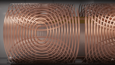
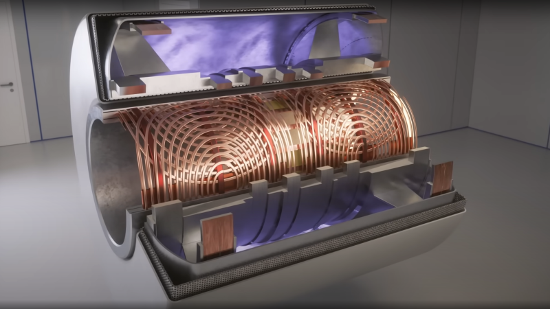
The basic principle of operation is to align the spin ‘axis’ of all the subject’s hydrogen nuclei using an enormous magnetic field produced by a liquid-helium-cooled superconducting electromagnet. The spins are then perturbed with a carefully tuned radio frequency pulse delivered via a large drive coil.
After a short time, the spins revert back to align with the magnetic field, remitting a radio pulse at the same frequency. Every single hydrogen nucleus (just a proton!) responds at roughly the same time, with the combined signal being detected by the receive coil (often the same physical coil as the driver.)
There are two main issues to solve. Obviously, the whole body section is ‘transmitting’ this radio signal all in one big pulse, so how do you identify the different areas of 3D space (i.e. the different body structures) and how do you differentiate (referred to as contrast) different tissue types, such as determine if something is bone or fat?
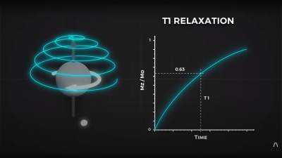
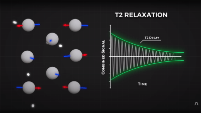
By looking at the decay envelope of the return pulse, two separate measures with different periods can be determined; T1, the spin relaxation period, and T2, the total spin relaxation period. The first one is a measure of how long it takes the spin to realign, and the second measures the total period needed for all the individual interactions between different atoms in the subject to settle down. The values of T1 and T2 are programmed into the machine to adjust the pulse rate and observation time to favor the detection of one or the other effect, effectively selecting the type of tissue to be resolved.
The second issue is more complex. Spatial resolution is achieved by first selecting a plane to virtually slice the body into a 2D image. Because the frequency of the RF pulse needed to knock the proton spin out of alignment is dependent upon the magnetic field strength, overlaying a second magnetic field via a gradient coil allows the local magnetic field to be tuned along the axis of the machine and with a corresponding tweak to the RF frequency an entire body slice can be selected.
All RF emissions from the subject emanate from just the selected slice reducing the 3D resolution problem to a 2D problem. Finally, a similar trick is applied orthogonally, with another set of gradient coils that adjust the relative phase of the spins of stripes of atoms through the slice. This enables the use of a 2D inverse Fourier transform of multiple phase and frequency combinations to image the slice from every angle, and a 2D image of the subject can then be reconstructed and sent to the display computer for the operator to observe.
See? It’s easy.
We cover MRI technology from time to time, here’s a little update on state-of-the-art resolution for those wishing the dig a little deeper.


“See? It’s easy.”
I remember a book I had on the math behind MRI. A phone book sized tome.
I think Dave was being facetious. To paraphrase a comment made in the video that mirrored the question I had while watching it: HOW did anyone or any group of anyones ever come up with this? Major “wow” factor.
I know the question is supposed to be rhetorical but.. I’ll take a shot at it. Tomography, like, the manual kind (not a CT scan) has been done almost since X-rays were discovered. It’s nearly impossible for me to describe in words but it’s pretty easy to understand (and do) in the flesh. From there, computed tomography is “just” the math to automate that process over and over, and the fast FFT math was already around from things like special analysis and converting time to frequency domain, something the readers of HaD would be more familiar with.
Then, the physics of NMR (nuclear magnetic resonance; also, same exact as for MRI but they don’t say “nuclear” because they don’t want to scare people) as used in chemistry and physics for, for example structure determination of organic compounds, has used the physics of excitation-relaxation. So putting those all together you can “easily” see how this stuff comes to be. In retrospect I’m sure the video that I haven’t watched yet does a better job explaining this.
Very well done!
I worked as a developer/researcher for a while in an imaging lab (MRI, CT, PET). For a brief, glorious time, I ALMOST understood the math and physics well enough to explain it.
Knowing how it worked didn’t diminish the wonder of it, though. Quite the opposite, in fact.
It’s kind of like when people watch the asianometry channel, and go, wow, how do they manage to do that? Lot of voodoo when it comes to the details.
Is “fast FFT” faster then FFT? :-)
I remember WHAY back in 1978 of an article in Popular Mechanics or Science that described the first MRI machine and the things (like niobium?) and heartaches of developing a medical diagnostic machine. BTW: they used an Apple ][ to display someone’s chest: nice chunky text graphics.
I’ve suffered from Crohn’s disease for 57 years. 20 years after my last surgery I started getting bowel obstructions and an MRI scan showed that I had a 7 cm stricture in my small intestine.
I worked as a technician for the FAA. Controllers told me they direct small planes around hospitals with mri machines. The magnetic field they produce interferes with compass headings.
That can’t be true. Well, that someone told you that is certainly true but the physics don’t add up. I’m literally looking at the engineering drawing for an unshielded MRI that has 200Gauss field and it is down to 1 Gauss at about 30 feet away. Modern shielded ones have 5 Gauss at the door to the scan room, a distance of maybe 10 feet from the magnet. I think it goes down by the fourth power. And field strength of earths magnetic field is 0.25-0.65 according to google-fu. I’ve been wrong before though.
TBF the FAA also seems to think that cellphones will throw off avionics, so they either operate on an abundance of caution or general ignorance.
No offense intended, but that’s BS. Clinical MRI magnets are shielded: they have trivial field strength outside the magnet room itself, and drop off quickly from there. They are below earth’s field strength within a few meters. Remember: field strength from a dipole drops off as the *cube* of the distance. Even unshielded research magnets drop off so quickly they are undetectable a few dozen meters away, let alone at (legal) aircraft altitudes.
However, a typical clinical MRI system operating at 3 Tesla transmits pulses of several kilowatts at 127 MHz, and receives fantastically tiny signals from the body at the same 127 MHz frequency. That’s smack in the aircraft radio band.
Despite the 100+ dB attenuation provided by the MRI system’s Faraday cage, aircraft at close range could still hear the MRI system and confuse the pilot, causing a crash. And aircraft transmissions on that frequency might still be detected by the MRI, potentially causing image artifacts and misdiagnosis. In practice it won’t ever happen, but lawyers exist.
It true. Even 7T magnets have very little strength outside the room.
I ran that past another controller friend of mine. Neither her, or her husband (pilot) had ever heard of MRI interference. It appears the original source, got one over on me.
Thanks for setting me straight.
Don’t get between your car keys and a running MRI machine.
Rule #1 is
The magnet is always on!!
Even if it isn’t running and it’s sitting there doing nothing.
MRI safety is crazy. There are multiple levels of security and physical site restrictions on who can be within certain distances.
While a key getting pulled in should be a “never event” I have seen glasses get pulled off. Low mass objects are not ideal but aren’t that bad. In general it is things like an errant non-MRI stretcher, a steel oxygen cylinder or something like that that results in a fatality. YouTube has videos of like a crescent wrench getting pulled with a literal ton of force.
And if you do have to “quench” the magnet it’s a HUGE DEAL. On top of dealing with whatever F-up lead to it and the medial
emergency, The helium displaces the oxygen in the room presenting a real asphyxiation risk. later the state and federal regulators investigate, the license is questioned… it’s a big deal.
Tell that to the guy who got shot by his own gun after entering the imaging room https://www.dailymail.co.uk/news/article-11733023/Lawyer-dies-gunshot-wound-MRI-machine-caused-gun-off.html
Poetic. I love it. And, as the saying goes, it’s a good start.
The Daily Mail isn’t exactly a trustworthy source.
It was a real case, with broad coverage in mass media here in Brazil.
Thank you Craig! Every opportunity to let people know the magnet is always on and can’t really be “turned off” is golden.
Our local Urgent Care center has a MRI. The sign on the wall warning about the Emergency Shutdown Control NOT shutting down the magnetic field says that fully shutting down will “Release Copious amounts of Helium out the roof vent” I’ve been told it cost about $5k in liquid Helium to restart after a full shutdown.
Or a butt-plug and an MRI Machine: https://imgur.com/gallery/rZswUpS
I came here hoping somebody would post that, that was both hilarious and pure horror at the same time.
It’s exactly how a pulsed induction gold metal detector works! Cool…
Close. It’s almost, but not quite entirely unlike how a pulse induction metal detector works.
MRI systems are very carefully tuned to NOT induce eddy currents in nearby metallic structures.
The RF field in MRI interacts with the protons in water (or fat). The pulsed LF field in metal detectors interacts with free electrons in metals.
RF coil and Gradient coils are separate and do different things. But I only worked on GE MRI systems.
Great article! I especially like your description of spatial encoding! I have a trio of bones to pick, though:
1. The transmit coil and the receiver coil are usually separate pieces of equipment. Most commercial receiver coils are placed directly on the patient and the “Body Coil” (a permanent transmit coil installed in the scanner gantry) performs the transmit function.
2. To the best of my knowledge, one cannot determine the T1 relaxation by measuring the decay envelope (which is the T2 relaxation curve) – T1 relaxation and T2 relaxation are two completely independent and simultaneous rates which are determined by independent phenomena.
3. Saying the proton emits an RF pulse is common and frequently found in textbooks (so you get a free pass!), I don’t find it does the best job of explaining what happens in the receiver coil. Immediately after a resonant RF pulse is transmitted into tissue a receiver coil will detect a decaying sinusoidal signal called Free Induction Decay (FID, exactly what’s shown in your T2 decay graph). The FID exists due to a synchronization of the phase of all the protons in the sampled tissue, causing the tiny magnetic contributions of each proton to sum into a Net Magnetic Vector (NMV) which rotates in a plane perpendicular to the main magnetic field. Very quickly after the RF pulse is stopped, the protons fall out of phase with each other, leading to a decrease in the signal detected by the receiver coil. You partially described this phenomenon in your explanation of T2 relaxation. Soon they all cancel out each other’s transverse contributions and no signal is detected by the receiver coil.
As an aside, most pulse sequences don’t make use of the FID directly, but rather recall the signal as an “echo” using additional RF pulses.
I’m the first to admit there is an overlap between RF signals and rotating magnetic vectors so my argument is a bit pedantic; it’s also quite a lot more of a pain to convey than “the proton emits an RF signal”. Nonetheless, I feel the NMV induction approach to signal generation more intuitively describes the behaviour of the FID, subsequently recalled echoes (which are a sinc wave rather than a regular decaying sinusoid), Specific Absorption Rate (SAR, a measurement of energy deposited into tissue), etc.
If you read all the through this – you’re a star!
Fantastic comment. Absolutely love HaD and you for stuff like this. Best.
Of course I read it all. Feel free to correct me, I’m not an specialist in medical imaging, just a general purpose EE hardware guy with a love for hacks. Trying to convey the complexity and subtlety of this subject in about 300-400 words can be a tricky at times. Feel sorry for the editor :D
This video adds some more detail that is missing from the one in the article:
https://www.youtube.com/watch?v=75_xWBwBB9g
That is, of course, an advert for Keysight: which doesn’t detract from its quality.
However I’d note that while, as an undergraduate, I never had cause to visit Peter Mansfield’s lab, he sure as Hell wasn’t using Keysight equipment :-)