Spinning hard drives are being phased out of most consumer-grade computers in favor of faster technology like solid-state drives and their various interfaces. But there’s still millions of them in circulation that will eventually get pulled from service — so what do we do with them? If you’ve got one that would otherwise be going in the garbage, they can be turned into some other interesting devices like this laser text projector.
 Even the slowest drives spin at around 5000 RPM, which is perfect for this type of application. The device works by mounting twelve mirrors, each at a slightly different angle, on a drum which is spun by the drive’s motor. Bouncing a laser off of the spinning drum results in a projection of twelve horizontal lines. By rapidly switching the laser on and off depending on which mirror it’s pointing at, the length of each line can be controlled.
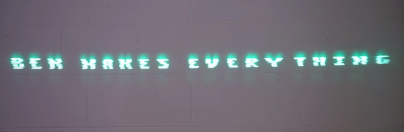
Thanks to persistence of vision, that allows you to show text on the surface that the laser is projected on. At speeds this high, it took [Ben] of Ben Makes Everything quite a few iterations to get it to a usable space. From sensors that were too slow to lasers not bright enough to 3D prints that were not accurate enough, he goes through the design of his build and the process in excellent detail.
After solving all of the problems including building his own constant-current laser power supply, and burning up a few laser diodes in the process, [Ben] has a laser projector capable of displaying readable text at a great distance which is also portable, running on a 12 V power supply. There are some possible areas of improvement that he notes as well, such as an unbalanced 3D printed part causing a bit of a wobble and the Arduino controller not being fast enough for more text. But it’s an impressive project nonetheless, similar to a two-mirror version we saw some time ago but with the ability to display text as well.
Thanks to [Måns] for the tip!


impressive, but your not getting my spinning rust anytime soon…
Yes, it’s Ok to have a TB or 2 for our fast storage for project files etc, and to boot off, but nothing compares to spinning disks for $/TB for things that doen’t need fast access. I have about 100TB of stuff, and I don’t need ssd speed – and cost – to store it…
The really sad stuff is tape – it just hasn’t kept up on the price/performance curve – so not much good for backup or archive…
No good for user’s with only moderate (~hundred TB) of storage needs. An LTO-9 drive alone is £5k, which could buy you ~200TB of spinning rust. And that would be high availability storage, rather than needing manual tape-swapping and a few TB of buffer storage to offload that tape data to.
Older tape drives can be cheaper, but then you also end up with smaller tapes that aren’t altogether that much cheaper. The £/TB of HDDs wins out somewhere around LTO-4 even without including drive cost, so for many users even LTO-5 is not going to save you any cash but instead just add headaches.
Oh. Yeah, for the home, or anything not enterprise production, LTO is not the way; agreed.
The death of spinning rust is greatly exaggerated. That BS about HDDs being dead by 2028 cracks me up.
I have 288TB and the cost of that in flash would be … intense. Even with current low prices. I do not see it getting massively better anytime soon.
I did a similar project about 20 years ago with an Arduino uno. based on
http://codinglab.blogspot.com/2010/09/diy-laser-projector.html?m=1
the limitations I ran into were the timing accuracy of the arduino, how fast you can turn a green laser on and off (red was fast) and of course no 3d printed parts for the mirror… nice to revisit this
20 years ago! That’s a really neat trick. Because the Uno was released only 13 years ago.
Blog was posted 2010 so 13 years ago. But I guess covid pandemic made it seem like 20 years ago
Ooooo! The different mirror angles for vertical scanning is very clever! I’d never have thought about doing it that way!
I wonder if it could be mounted inside a toilet bowl (IP65 case?) and project some funny jokes on toilet seat cover while you’re doing pee. Could help relieve morning anxiety and anger attacks.
Use a motion sensor, a celling mount and a mirror to reflect the message into the bowl and it would be a piece of piss.
Does one need to stand closer if one has a 9-inch hose?
“Don’t look here; the joke is in your hand.”
Millions? Surely you mean many orders of magnitude more than that?
Now I’m super curious about how many hard drives are spinning right now. Hah, how much kinetic energy is stored in spinning platters at this moment?
You can buy a whole bag of lasers for what, $10? Just make a stack of eight or more lasers to draw all the scan lines at once. Easier and much brighter.
If you read the article, you would maybe have stumbled upon the other limiting factor. Solving that means you are beginning from scratch and design your own version. Also lining up all those lasers is a completely different beast…
lining up the laser will require a similar rig to the existing one
Perhaps, but lining up multiple lasers on a fixed part of the chassis, offers up many different possibilities than lining up mirrors on a spinning disc.
Wouldn’t a front facing IR-Emitter and Phototransistor use the mirrors themself instead of tabs?
How would you handle the index pulse then?
An optical “start of scan” pulse of of each mirror helps to handle the left-right jitter problem. The 12-mirrors only need to be mounted around the ring at approximately 360/12 = 30-degree. Each mirrors will tell you precisely where it is an when it comes into view. The “index” pulse for mirror-1 can be relatively crude using the same optical interrupter vane. It only needs to tell you that you at on mirror-1, but once again the precise “start of scan” come from the mirror itself.
I wonder whether it’d be feasible to get a custom polished mirror wheel with each facet at a slightly different angle…
but then again, you simply could buy one galvo for vertical deflection and use a mirror wheel from a laser printer…
I don’t think it’d be difficult at all. Cast the wheel out of resin to get your angles set, polish the facets, electroplate them, then polish again. Or maybe it could be cast in aluminum for stiffness and to save the electroplating step, although it might be too heavy for the drive motor.
Ben this is brilliant. There is a lot of talent shown here. Your persistence is also amazing.
That’s how it works!
I successfully built a similar projector but instead of spinning mirrors I used 2 orthogonal mirrors, each mounted on a harmonic oscillator powered by electromagnets.
The oscillating mirrors had to be tuned to the correct frequency by adjusting the weights (cutting small pieces of the mirrors) or by changing the spring constants (also removing pieces of the spring material).
I remember having to use a phone app to do Fourier analysis on the sound of the oscillators to check wether they resonnated at the correct frequencies.
Corrections had to be made to linearize the curve of the sinusoïdal motion.
I made it very compact, but was limited by timing constraints of the ATMega328. One of the drawbacks was the limited divergence of the beam projected, as high mirror frequencies produced limited angular sweep. Maybe a lens could correct that easily…
It was for a national engineering school contest, a few years ago.
I don’t know why this technique has not since seen widespread commercial adoption
I’ve had a similar gizmo on my to-do list for some time. In the few brainstorming sessions so far, I have not yet come up with anything super satisfactory for getting a decent divergence angle. Several rabbit trails led me to multipart custom figured optics, which take a helluva long time for a one off.
This looks VERY similar to the Scophony mechanical TV designs of the 30’s
I was going to say that, but could not remember the name, some people are still making mirror drum mechanical televisors.
So, if 1080, or 2160 mirrors were mounted on the rotating platter, you could have HD, or UHD pictures. Now all that is needed are 3 lasers (Red, Green, and Blue) . Vouala! A full Highdef projector, and probably bright too (depending on the lasers used).
Laser video projectors were A Thing a few years ago. They seem to have become less popular in recent years, I’m not sure why. E.g this one has been discontinued: https://www.aaxatech.com/products/l1_laser_pico_projector.htm
I wonder about just using multiple lasers. If you had say 9 of them in theory you could do a 6×9 font in one pass. It seems like it would be brighter without needing a big laser, and all the stuff that had to be angled precisely would still be there, but at least it would not be spinning.
The issues that come to mind with that, are trying to get the 9 in close proximity without having heat issues, also physical size is problematic, then you’re into more optics again with beam collimators etc.
You can pull multi-sided mirrors (and sometimes the motor too) from laser printers for these types of solutions. Fun stuff.
This reminds me of this 1933 mirror based mechanical TV.
https://www.youtube.com/watch?v=eoOe2LcSQNQ
Ben encountered and solved some problems that laser printers needed to address 40-years ago. Such as the Canon print engine widely used by HP LaserJets and Apple LaserWriters.
With laser printers, prior to each page, a software feedback loop is created where the laser is calibrated to the correct power using the laser’s own built-in photo diode. Then, the calibrated value is held constant by a D/A convertor as the page is written. Further, a first D/A converter sets a bias current just *below* the threshold needed to lase (likely several dozen milliamps). This bias current is always present. Then a second D/A is supplies only the *additional* current needed to take the laser from the bias level to the powered level (this is only a few milliamps). Typically that second current isn’t even switched on and off, rather it is allow to reach the laser, or shunted away. It is a LOT easier to rapidly modulate that small incremental current with NO feedback loop from the diode laser’s built in photo diode, than it is to switch the full current and have to include the photo diode in the feedback.
As a bonus, in Canon’s laser printer system, the original organic photo conductor drums had a lot of variation in sensitivity. This would have made them very expensive with a high reject rate. What Canon did was introduce two plastic tabs on the toner cartridge, that contacted two micro switches in the printer. In effect, each toner cartridge told the printer if is Low, Medium, or High sensitivity. Then the laser diode calibration software added an additional step to the D/A current calibration described above to compensate for a specific cartridge’s sensitivity. So a broader range of toner cartridges could be use, that otherwise would have been rejecter as too Low or too High of sensitivity.
And the switch coding was such that if NO toner cartridge was present, both switches would be off, and the software would complain to the user accordingly.
Here’s a quick thought about how to switch the laser on/off: Use the same constant current source to power the laser continuously. To switch off the laser, ground the current source output, bypassing the laser. A refinement would be to draw enough current through the bypass to pull the output voltage below the lasers minimum threshold voltage instead of all the way to 0V (reduces voltage transients across the diode).
This was written from an assembly/C++ point of view. You may not have some of these options using Arduino libraries.
You might be able to get more stable timing of the mirror system by looking for a mirror drum index pulse (once per revolution), then basing all the pixel timing (all scan lines, all characters) from that one trigger (is it really necessary to detect each mirror?) That index pulse allows you to measure the drum speed, and possibly fine tune pixel timing.
Interrupts (exceptions) take time to branch to interrupt code, execute the code, then return to the main code. This makes it difficult for the main code to assure accurate timing during timing critical processes. Find a way to avoid branching to interrupt code.
Look at how LCD controllers (and video character generators) store and output their character sets (each character is an array of pixels stored in bytes, the first byte being the top scan line of each character, the second byte being the second scan line, etc.). In other words, reduce the run-time computing demands by using preset pixel maps (data lookup tables). 12 scan lines > 12 bytes per charactor. The last byte is used for descenders (lower case g, q, y, and commas). The last bit of each byte is the dark space between characters.
Consider using a serial data peripheral to output pixel streams. A master SPI peripheral can output 1 byte of TX data with perfect timing, but may lack a buffer to queue up the next byte for transmission. A master USRT may buffer 1 or 2 bytes ahead of time. In both cases, you wouldn’t care about the serial clock that is also being generated. Clock sources: rather than divide down the system clock by 1, 2, 4, 8, etc, consider using a timer/counter as the SPI/USRT clock source (allows for fine tuning the pixel timing).
Where to get the serial data? Use the character pixel maps described above. Copy from charactor set storage, then write to the USRT/SPI peripheral.
Feeling adventurous? Use a video character generator.
Nice to see the mirror drum design revisited. It’s a well-built construction!
However, from the video it sounds like you came up with the idea, even though we’ve seen this principle being used for the last 10 years at least.
For example: https://www.youtube.com/watch?v=vvbzIy2U1J0 or https://www.youtube.com/watch?v=7rWy6-go_y8
I would recommend doing a little research before starting a new project. It can only benefit you since you can learn from other people’s mistakes.
I’m pretty sure they would be happy if you acknowledge and reference their original ideas, which you improve on.
After all, that’s the beauty of being part of the DIY maker family :)
By the way, if you ever decide to switch to a more powerful microcontroller like ESP32, feel free to use my PCB design files and source code as a starting point. I’ve built an open-source Wi-Fi controlled laser projector last year – https://hackaday.com/2022/11/02/laser-project-relies-on-steppers-rather-than-galvanometers/
All hacks have already been done:
I liked this idea when I first heard about it in 2012:
https://hackaday.com/2012/09/14/16×8-pixel-laser-projector/
Hackaday covered it again in 2018:
https://hackaday.com/2018/04/20/laser-projector-ditches-galvanometer-for-spinning-drum/
After looking at the video, recognizing all the challenges and solutions and scrolling through the posts, I see someone referring to my laserproject post of 2012 (you, nice!) For me (and I think this goes for a lot of hackers) it was a personal rite of passage to try and build something (to later write about it in hopes of being mentioned on Hackaday). I think back to that period with pride and a smile!