FPGAs are supremely flexible and powerful devices. However, they usually come in QFP or BGA packages that are altogether difficult for hobbyists to play with. The DIP-FPGA breakout board aims to solve that problem by using a carrier PCB to put an advanced chip in a friendlier form factor.
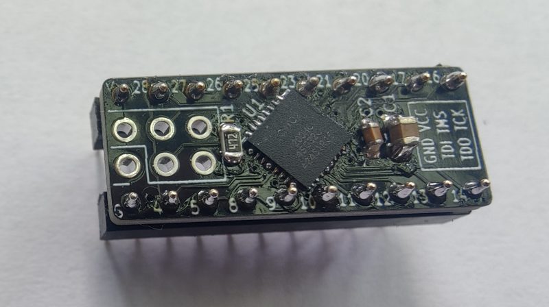
The board itself fits a DIP-20 form factor when soldered up with regular-pitch pin headers. It features a MachXO2-1200HC FPGA from Lattice Semiconductor. That’s the same chip as used on similar the TinyFPGA A2. With 18 GPIO, a DIP-20 layout is just about enough pins to take care of business. It’s intended specifically for use on breadboards or via regular IC sockets. There’s also a six-pin programming port laid out on the board that you can use with pogo pins or header connectors as you desire.
If you want to do some fancy signal stuff in an easy-to-prototype form factor, this could be the setup for you. If you want to buy one ready-made, they’re available on Tindie for the curious. In the meantime, consider whether this beefy FPGA Arduino concept could also propel your next project to greater heights.


Looks quite a bit like the Digilent Cmod boards. My favorite form-factor for playing with FPGAs.
The Lattice Semiconductor MachX02-1200U series has 1280 LUTs.[1] The MachX02-1200UHC sells for roughly $16 bucks each in small quantity.[2] So that $20 pre-soldered MachX02-1200UHC DIP breakout sold on Tindie looks like a square deal, but it ships from Austria and I live in Florida.[3]
* References:
1. Lattice Semiconductor MachXO2 Device Selection Guide
https://www.latticesemi.com/en/Products/FPGAandCPLD/MachXO2
2. Findchips XO2-1200U
https://www.findchips.com/search/XO2-1200U
3. MachX02-1200UHC FPGA breakout board in DIP-20 form factor
https://www.tindie.com/products/c0pperdragon/fpga-breakout-board-in-dip-20-form-factor/
But the million dollar question is: “Are it’s IO-pins 5V compatible”
Couldn’t find your million dollar answer in the datasheet, which I guess means “no”.
But 3.3 V isn’t even the new hotness anymore, right?
but if you want it to replace a vintage chip, pal, gal or 74 logic whatnot, 5V tolerant is a must.
Which, if you’re playing with DIP parts, is highly a probable thing
Why? If you need the DIP format for working on a breadboard, what’s so hard about sticking a 5V-tolerant input buffer there when you need one? I mean, if it’s slow and you’re lazy, a diode works fine as a level translator with the Schmitt trigger FPGA inputs plus its internal pullup.
The only time that would be a problem is if this would be trying to drop-in replace something, which I’m pretty sure it isn’t, given that it doesn’t use the standard opposite-corner pins for power/ground that most 74-series chips do.
Better to use a CPLD in that case, because they are ready on power-on, while FPGAs need programming and should not be handling I/O until programming is finished
But for the kind of projects this will likely be used in 5V is often required. The value of this board could be increased greatly by somehow adding level shifting circuitry. Just not sure where they might fit here, maybe on the reverse side?
I don’t understand why you wouldn’t just put it on whatever board this is interfacing with. You can get buffers with 5V tolerant inputs in DIP packages if you want to build the whole thing up in a breadboard. I mean, if the signals aren’t that fast you can always just use a fast diode: there are Schmitt triggers and pullups in the FPGA.
Level shifters that can deal with the poor signal quality on a breadboard would significantly limit what the FPGA is capable of doing.
If you like living on the edge, you can also just play around with series resistors to see at what value the clamp diodes in the inputs keep the voltage below the max input (3.75V). Manufacturers have generally taken those details out of datasheets for a long time now, but it still tends to work.
3.3V *outputs* are almost always good enough for devices that want 5V in.
I think the point is when using it as a replacement for no longer manufactured chips where you are just sticking it in an existing design and you aren’t modifying the PCB.
Yeah, but that’s not what this is for, as far as I can tell. If it did it’d probably have power/ground on diagonally opposite corners, at the very least.
If you really wanted to design a board to replace an existing DIP component it’s not that hard to deal with 5V signals, but you probably wouldn’t make a “generic” board to do it. Even in an FPGA the pins aren’t all totally general-purpose, so you’d want to make sure the pinout matches anyway.
Yeah I assumed that this small DIP form factor is dictated by the need to replace an arbitrary weird chip in an old computer, or other device. In that case 5V TTL compatibility would be really useful.
I can’t really see what it’s for otherwise, because if you’re not replacing an old chip, why bother with such an inconvenient package.
The data sheet answers: no.
so where do I get my money?
5V compatible?
That’s the same question I ask, whenever I see an FPGA board with Arduino Shield pins for IO.
And – no, when I check schematics (if available) there is no level shifting, or protection, on those IO pins.
Curious also whether you have to supply an external flash chip for the fpga bitstream, or if that’s on board or on chip. 20 pin form is nice, but in most vintage h/w the most complex 20 pin device you run into were the custom “glue” chips, often PAL things like 16L8 and etc – not much challenge for an fpga. Where an fpga would really match the challenge would be on the bigger parts like the C64 PLA or better yet 6526. Or the Apple IWM.
Anyway, looks handy.
MACHXO FPGAs have an embedded FLASH, no need for an external one :)
QFP difficult? Even 0.8mm pitch QFP-32? Kind of difficult to evolve these days and not solder SMD…
Especially that you’re selling these, I recommend cleaning up the flux before your next photo shoot. Even better to use a stencil and hot air station to avoid hand soldering the SMDs… I’d worry about quality given just what my eyes are telling me.
Yeah I did think that too, it looks like a janky, temporary fix rather than a product that is getting sold. Not to mention if they are producing these in any reasonable quantity they would be faster using a stencil and hot plate or IR oven rather than doing it by hand with a hot air gun. Or just see if the PCB manufacturer can assemble it for you.
In terms of specs the FPGA is not great but might be enough for some basic functions. Slightly bigger (physically) but much more powerful FPGAs are out there, there are ones that can fit on a breadboard like a MCU dev board. Sipeed has some with their tang nano series. Sipeed are also going to create their tang primer 25k which has 25k luts and its SOM is not much bigger than a keycap, although it’s connectors may be difficult to use.
I don’t know where you got the 25K number from. They currently make the Primer 20K and they were, last time I heard, thinking of using the GW2A-55 FPGA with 55K LUTS. The 20K is on a SODIMM sized module.