When first starting an electronics project, it’s not uncommon to dive right in to getting the core parts of the project working. Breadboarding the project usually involves working with a benchtop power supply of some sort, but when it comes to finalizing the project the actual power supply is often glossed over. It’s not a glamorous part of a project or the part most of us want to be working with, but it’s critical to making sure projects don’t turn up with mysterious issues in the future. We can look to some others’ work to simplify this part of our projects, though, like this power supply from [hesam.moshiri].
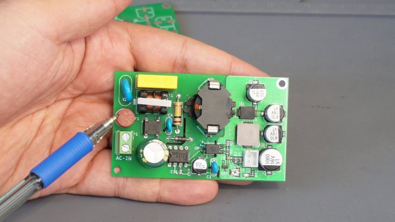
The power supply is designed around a switch-mode topology known as a flyback converter. Flyback converters work by storing electrical energy in the magnetic field of a transformer when it is switched on, and then delivering that energy to the circuit when it is switched off. By manipulating the switching frequency and turns ratios of the transformer, the circuit can have an arbitrary output voltage. In this case, it is designed to take 220V AC and convert it to 8V DC. It uses a simplified controller chip to decrease complexity and parts count, maintains galvanic isolation for safety, and is built to be as stable as possible within its 24W power limitation to eliminate any potential issues downstream.
For anyone trying to track down electrical gremlins in a project, it’s not a bad idea to take a long look at the power supply first. Any noise or unwanted behavior here is likely to cause effects especially in projects involving sensors, ADC or DAC, or other low-voltage or sensitive components. The schematic and bill of materials are available for this one as well, so anyone’s next project could use this and even make slight adjustments to change the output voltage if needed. And, if this is your first introduction to switched-mode power supplies, check out this in-depth look at the similar buck converter circuit to better understand what’s going on behind the scenes on these devices.


This is why I don’t own a fancy regulated power supply. Most of the time, the power supply and other power handling stuff IS the hardest part of the project. If it can’t run on a cheap ISDT hobby charger in DC voltage mode, or any of the USB-C voltages, then that’s the first issue with my design and I need to fix that.
There are uses for the nice power supplies, but I don’t get why people say they’re so essential, except for testing industrial stuff.
Wait a second, how do you know for sure it’s reliable? There is no indication of extensive testing and it’s just one guy.
Reliability is a lot harder than that.
I also struggle with this, i am trying to make ventilators that get built into a wall. Not the power supply of course. And everything can be removed replaced etc however there is a customer perception that anything not made by a normal company with mass manufacturing is sketchy.
We can’t schlep it like this. You don’t know this is safe or reliable, not yet. It has to be reviewed and made and used many times in many many contexts by many people in different ways before you can say that.
“ventilators that get built into a wall” – yuck – breeding grounds for respiratory MONSTERS!
You can’t know it’s reliable and safe yet. I wrote a longer detailed comment but your commenting system lost it.
I’m not sure why one would bother to DIY something that is safety critical when open frame DC/DC converters are ubiquitous and have already gone through much compliance testing. Some things one can DIY for sure, but an offline PSU really isn’t one of them unless there are very unique and specific requirements.
I love these projects where someone just shows off what they built, without publishing the schematics – probably thinking that they have found the secret sauce – giving no chance to others to learn.
On this note, Hackaday could be a little bit more upscale about what to publish – i.e. the snake oil -no schematics, nothing- type electronics projects are not worth posting; these projects make the content look lower quality IMO.
@szoftveres, may you missed the published schematic – please see here: https://www.pcbway.com/blog/technology/220VAC_to_8VDC_24W_Flyback_Switching_Power_Supply_88bf6837.html#:~:text=Circuit%20Analysis
Just bearing the HACKADAY.IO moniker alone is enough to gain entry – actual content be damned.
We build a lot of home brewery controllers, boil controllers, still controllers and stir plates and we use over 500 12V power supplies a year. So, I definitely have an informed opinion of low cost Chinese power supply reliability. I’ve experienced and disassembled plenty of failures. Most of the time, over 90% of the time, a failure was caused by an open solder joint.
The power supply we use today is waterproof and I’ve not seen a failure in at least two years. But I don’t use this power supply because it’s waterproof, I use these because of how the manufacturer makes them waterproof – they pot them. And the potting immobilizes all the internal parts, eliminates any open solder joints because the internal parts can’t move.
We buy our power supplies 300 at a time from a Chinese supplier but here’s a link for the same type of power supply on Amazon.
https://www.amazon.com/SHNITPWR-Waterproof-Transformer-110-260V-Converter/dp/B07X3YV3CR/
I’m not questioning your experience, but potting can in fact have the opposite result to your experience and lead to component failure, in particular if the device is subject to thermal cycling, as there is some expansion and contraction. Leaded components may flex, leading to intermittent failure (picture bending a wire back and forth repeatedly, even if just a small amount).
I agree that there are positive and negative impacts to all design changes. But I’m not adding potting to the power supplies I buy. They ship from the manufacturer this way.
Also, you need to understand the failure modes I was experiencing. The failures weren’t caused by no solder, they were caused by cracked and broken solder joints. All of the power supplies worked when we shipped as we tested the product with its power supply before shipping. These failures were common across multiple suppliers which is what led me to this solution.
The waterproof power supplies cost about twice as much as the other supplies and the solder joints may be as poor in these power supplies. But potted parts can’t move which means the solder joints are less likely to crack. In other words, problem solved for about $3.00 a controller.
I’m not implying you’re reworking the devices. There’s a good chance that the manufacturer is putting more attention to the assembly and QC process, and that potting isn’t really a factor in the reliability change you experience. Ask yourself why any parts would be moving on the PSU PCB in the first place. They’re in an enclosed chassis, right? A good PSU should be able to run years and years without issue.
Re: potting and thermal cycling isn’t just a “could happen” — it’s an issue which impacted the company I work for about 10 years ago, resulting in $millions in write downs for RMAs, and resulted in a change of potting compound (from a rigid type to a silicone based one that is elastic). Conformal coating is another option for adding moisture resistance. FTR, FA with rigid potting is a bear because the process of digging out the potting can be abusive and lead to component damage, which can obscure the actual failure (though most failure modes are well enough understood after a few million units are produced )
I’ve had two different garage door openers fail because of a cracked through hole joint. The major vibrations of the opener after a decade seems to open up certain joints. I don’t think it has anything to do with heat cycling, because the opener shouldn’t operate long enough to get too hot. Seems like they should pot the garage door opener electronics to prevent this failure mode!
Part of the issue is the Chinese use single side boards and there is a strain point in the web of solder between the leg of the hairpin formed parts, the interface wires and the pads on the board. Thats likely where your garage door opener failed and that’s where I saw all of my failures. Switching to potted power supplies solved this issue for me because the potting removed the strain from those solder joints.
Another poster commented on “cheap Chinese power suppies” and said something to the effect of “Use quality power supplies”. I would tend to agree with him except I bought two expensive 12V power supplies. And when I cut them open I found the exact same type of construction inside. They were made of the same brown single sided boards with some hairpin bent components and input / output wires hand soldered through the board.
Just a heads up, but the power supply you linked lacks the appropriate approvals. The items states “Certified by FCC CE ROHS” … FCC has to do with emission levels (radiated and conducted) and nothing to do with electrical compliance standards. Even so the item does not state which FCC class the unit complies to. “CE” is a joke and in most cases is self certified from vendors abroad. Installing and using these power supplies may open you up to liability should things go awry.
Instead of saving a few $ and opening yourself up to potential liability issues, it would be far more prudent to use a power supply that has the appropriate approvals and that is approval registration verified. The few $ more for the appropriate power supply can simply be added to the final product cost and for 500 units a year it would not really be that much of an impact.
In the Long Ago days of CRT TV’S, I found many problems associated with the flyback transformer.
Using horizontal sync pulses, these generated several kilovolts for the tube – and vibrated enough to produce a high pitched ringing.
Don’t underestimate the value of potting compounds.
I have wanted to create a flyback power supply for the longest time but I cannot stop worrying about the snubber design, and not knowing the exact inductance of the transformer. LTspice simulations don’t help when they tell me the leakage inductance will cause the circuit to blow up because the switching node will reach over 2kV.
Its funny because I have been told that I may not need the snubber at all if I am not dealing with low currents and low duty cycles. I guess its one of the things that I can only experience by building it
Flyback supply design and implementation can be a real can of worms at the best of times. Would you not be better off using one of the forward converter topologies?
As for leakage inductance, if you’re still stuck on making a flyback converter you might want to start with a low-power, low-voltage design and work your way up. Use a (well-protected) ‘scope and measure the spikes. Get a feel for how the transformer construction and turns ratio affect the leakage inductance. Simulation is awesome, up to a point, but a working prototype tells you so much more, especially when it comes to inductive components.
I don’t have a lot of experience with snubbers – you probably know more about them than I do. If you need some more info, you might want to look at this: https://www.ti.com/seclit/an/slup100/slup100.pdf
I work in this area, as an applications engineer for switching power controllers. We have PhD’s with years of experience designing the circuitry, and probably 70% of the time we end up changing the design snubber values once we’ve tested/characterized the boards. The implementation of the control loop has a huge effect on the system behavior and you can’t really model this in LTSpice. We use an in-house simulation tool that our IC designers set up for us, that has access to the actual silicon design, and even that isn’t accurate enough to get better than close. It’s an iterative approach.
Just looked at the writeup in the PCBWay blog – DO NOT BUILD THIS THING AS-IS! The PCB artwork has a silly design flaw near the optocoupler, making the isolation gap under the coupler ineffective. This will never pass UL or VDE/IEC requirements.
I am all for DIY and learning and so by all means build your own supply for this purpose. However, it makes absolutely no economic sense to make your own mains powered supply that will lack all the formal approvals that are typically required in many jurisdictions. If something should go awry and a fire results, etc your home or business insurance can void your policy. Meanwell and others offer open and closed chassis mains powered power supplies for relatively small $… $12-$20 … and they have all of the approvals in place. By the time you build your own including parts, labor, etc you will probably exceed the cost of buying an already approved supply and have a safe and reliable device. However, YMMV.
Beware of cheap supplies from China though – many of their “approvals” aren’t worth the (counterfeit) stickers that claim they’ve been approved.
I don’t mean to nitpick, but shouldn’t there be a thermal fuse near the crowbar? Or a crowbar with integrated thermal protection?
Pretty nice to see some open designs for AC-DC and it’s a great learning experience, but I’d never put something like this in a product.
To me it’s much safer to use an AC-DC module from a known brand like Meanwell. They don’t cost a lot and have been worked on by whole departments, have all the certifications etc. Unless you’re making thousands of something the economy of not using a module isn’t worth the headaches and risk.