The magnetic compass has been a crucial navigational tool for around a thousand years or so, perhaps longer. While classical versions still work perfectly well, you can now get digital magnetometers that work in much the same way. [mircemk] decided to whip up a digital compass to demonstrate the value of these parts.
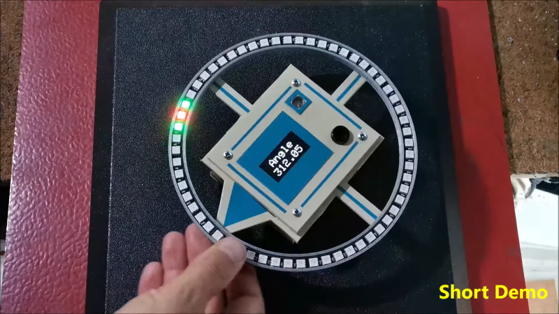
The build uses a HMC5883L magnetometer. While this can detect magnetic fields in three axes, just one is necessary for building a device that operates akin to a traditional compass. The output of the device is read by an Arduino Nano, which is hooked up to a string of WS2812B LEDs and a small OLED display. The LEDs display the bearing of magnetic north, while the OLED screen shows the current angle between the compass’s arrow and magnetic north.
It’s a tidy build that would be a great educational resource for teaching both electronics and navigational skills. We’ve seen similar projects before, like the hilarious Pizza Compass. Video after the break.


Very cool! Surely it’s not accurate to two decimals?
Either way, and especially if it is, something I find neat about precision measurements of the magnetic field is, they let you get your rough latitude/longitude in a somewhat different way than old fashioned navigation.
(In the old days) Longitude reduces to the problem of keeping two synchronized clocks – easy for reasonable precisions now. You can imagine as a simple example that if you had a sundial which said it was noon while your clock said it was 1pm, then you must be one hour west of where you set your clock. You just convert the difference to degrees. Latitude isn’t quite as easy as that to do visually. It normally would have been done by finding the height of the sun or stars above the true horizon, but the horizon or the sun is often obstructed, and even if it isn’t, it’s easier to tell which direction the sun is in than how high above the horizon it is. But the magnetic field angles into the earth – it’s parallel to the surface at the equator and straight down at the north pole. So with calibration, you can work backwards from the longitude and the inclination to find the latitude. The device operating the digital magnetometer could host a correction table, probably. It’s predictable, but it’s not as simple as a 45 degree angle at a 45 degree latitude.
Really something with a clock, a magnetometer, an accelerometer, and maybe a barometer might be enough for coarse three-dimensional navigation if there’s ever a need to avoid GPS. Tiny low power balloons that pop when reaching the end of their intended area? With the magnetic latitude, it’s longitude that’s harder without a human around. Direction finding a terrestrial radio source would be very coarse, though it’d help. At that point you’re better with GPS. Hmm… There’s probably a way.
“Really something with a clock, a magnetometer, an accelerometer, and maybe a barometer might be enough for coarse three-dimensional navigation if there’s ever a need to avoid GPS.”
You are talking dead reckoning which is really hard. GPS is going to always trump that. And while a pressure gauge can give you relative elevation, it can be way off the absolute elevation. Add to that magnetic declination. At the Seattle-Tacoma International Airport the declination is over 15 degrees. So even if the dead reckoning was working perfectly, you would be off course because magnetic north would be off by over 15 degrees.
Oh, you always want to correct for declination. And unlike the dead reckoning systems I’m mainly thinking of, the accelerometer was for orienting the magnetic field vector WRT the surface which doesn’t take a fancy one. GPS is always going to be way better when available, but I’m really assuming you have the readily available charts for declination, inclination, and maybe intensity saved or programmed into the device rather than taking the naive approach. (https://en.wikipedia.org/wiki/Earth%27s_magnetic_field#Geographical_variation)
That way if you can assume or guess a few simple things like what hemisphere you’re in, what your longitude is to the nearest hour or half-hour, and what the date is, you can make a good enough declination correction to bootstrap another round of calculations with a more accurate version of north. At least it doesn’t drift the way normal accelerometer integrating would do. https://en.wikipedia.org/wiki/Magnetoreception is also interesting.
Actually you do need all 3 axes to make a good compass. Depending on your latitude the earth’s B field points down in to the ground or up from it at different angles, to reliably track north with digital sensors you need to measure all 3 axes of mag field and compare them to a gravity vector from an accelerometer. You’ll also often need all 3 mag axes for the purpose of calculating the correct compensation coefficients to remove any compass offsets caused by soft or hard iron distortions within thereference rame of your measurement device.
The algorithm is as follows:
West=CrossProd(MagVecArr,AccVecArr); //sets values in to West
Normalise(West);
North=CrossProd(AccVecArr,West);//gives us a North direction within the x-y plane
Normalise(North);
//now some double checking, to ensure North is pointed North not South
float CheckerVal=DotProd(MagVecArr,North);
if(CheckerVal<0){
North[0]=0.0-North[0];
North[1]=0.0-North[1];
North[2]=0.0-North[2];
}
float BoardOrientation[3]={1,0,0};
float East[3]={0,0,0};
East[0]=0.0-West[0];
East[1]=0.0-West[1];
East[2]=0.0-West[2];
// Arctangent of y/x
float Heading = (atan2(DotProd(East,BoardOrientation),DotProd(North,BoardOrientation))*180.0)/M_PI;
I had a section in my thesis about how to make use of an existing open source toolchain to find compensation coeffs by whirling the compass device (embedded in a robot) round in all 3 axes while recording compass data continuosly, and then implement this heading calculation to within a few degrees accuracy despite having motors a few cm from the magnetometer/accelerometer chip.
Is it possible you share the document?
“While this can detect magnetic fields in three axes, just one is necessary for building a device that operates akin to a traditional compass. ”
Think about it. How is that possible? Even for a compass that needs to be used flat to the surface of the earth you need to take the inverse tangent of the ratio of the 2 magnetic sensors parallel to the surface of the earth. (BTW, For anyone actually writing the code for them selves, use atan2() to get PI to -PI (full circuit) results. Otherwise if you use atan() you will need to write extra code to figure out which quadrant you are in.)
Flat Earth maybe? XD
You’d have to rotate (holding flat to the surface) to the point of maximum positive value on the single axis, and then physically take angles off from North rather than trying to measure them with the sensor. But yeah, having all three is much better.