Debugging a Raspberry Pi Pico is straightforward enough; it simply involves hooking up something up to the USB and SWD pins. [Mark Stevens] whipped up the PicoDebugger to make this job easier than ever before.
The Raspberry Pi Foundation developed the Picoprobe system to allow a RP2040 to act as a USB to SWD and UART bridge for debugging another Pico or RP2040. The problem is that hooking it up time and time again can be fussy and frustrating.
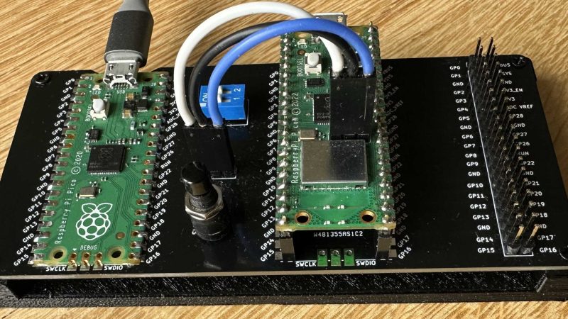
To get around this, [Mark] whipped up the PicoDebugger board, which directly connects most of the important pins for you. Drop a Pico into the “Target” slot, and you can hook up the PicoDebugger to its UART lines with the flick of a DIP switch. The SWD pins can then also be connected via jumpers if so desired. It also features a 2×20-pin header to allow the target to be wired into other hardware as necessary.
It’s a neat project, and it certainly beats running a bird’s nest of jumper wires every time you want to debug a Pico project. Simply dropping a board in is much more desirable.
We’ve seen some other neat debug tools over the years, too. If you’ve got your own development productivity hacks in the works, don’t hesitate to let us know!


Cool. Looks like it could be very useful.
That said, I believe the “Raspberry Pi Debug Probe for Pico and RP2040” is an off the shelf solution too. I have one, but haven’t had to use it … yet!
https://www.adafruit.com/product/5699
Same here, but I like the laid out design of this one.
The normal Picos seem to come without a populated SWD socket. Also the Pico W seems to have little space for fitting a SWD-JST-socket due to the SWD pins being close to the WiFi module.
Further research reveals there are two types of Pico boards. Those without soldered on pin headers, and those with them. However the footprint of the debug pins on the unsoldered version is not compatible with the footrpint of the SWD plug: JST-SH.
JST-SH has a 1mm pin to pin pitch, while the header free boards have a 2.54 mm pin to pin pitch for the debug pins.
In short, not all boards have a JST-SH socket (nor can it be added later), so you’ll have to hook up several wires each time.
Also, even when the board has a built-in JST-SH socket for SWD debugging, you still have to connect the UART pins manually.
So you could use the switches to connect/disconnect as needed.
Maybe a SWD cable with a switch would be easier (and updated Picos with a soldered on SWD socket).
Did the exact same project last year!
https://github.com/Savage-Company/rpi-pico-devboard
Very nice!
Porting industrial-strength Intel MCS BASIC-52 using transparent portable c with modules no greater than one page of code to the Pico good idea?
BASIC-52 is interactive and batch. Incremental compiles too.
Adding figForth C, and , would make a machine code generator.
BAASIC-53 is a stand-alone interactive/batch OS.
No external debugger needed.
These technologies were advancing in the 1980s until stamped-out by
the c/c++ industries n ~1991.
Bugs [UPDATES] and malware now causing c/c++ industries issues in 2023?
i don’t get it? what’s the downside to just connecting the 3-wire SWD while it’s in situ? do you need those pins for anything else? is there some problem with having USB and SWD connected at once?
the only thing i’m coming up with off the top of my head is matching ground?? (i imagine using a laptop on battery power solves this?)
the other thing i’m seeting is a reset button?
i’m just not understanding what the lack is in the picoprobe that this corrects
Not all Picos have an SWD socket, nor can it be added. For the rest, see my comments above. But it still doesnt seem like an ideal solution.
thanks but i still don’t understand. why do you need to disconnect other than at the end of your project? and why not just make the different cable, if the pin spacing is wrong?
It is all about convenience and reducing the amount of clutter on your desk. It is super handy to be able to just throw a Pico into a debug environment knowing you do can just connect to the board through one cable.
Sometimes it is the simple things that just make life a little easier.