For those looking to add wireless connectivity to embedded projects or to build IoT devices, there is perhaps no more popular module than the ESP32. A dual-core option exists for processor intensive applications, the built-in WiFi and Bluetooth simplify designs, and it has plenty of I/O, memory, and interoperability for most applications. With so much built into the chip itself, [atomic14] wondered how much support circuitry it really needed and set about building the most minimalist ESP32 development board possible.
Starting with the recommended schematic for the ESP32, the most obvious things to remove are a number of the interfacing components like the USB to UART chip and the JTAG interface. The ESP32 has USB capabilities built in, so the data lines from a USB port can be directly soldered to the chip instead of using a go-between. A 3.3V regulator eliminates the need for many of the decoupling capacitors, and the external oscillator support circuitry can also be eliminated when using the internal oscillator. The only thing [atomic14] adds that isn’t strictly necessary is an LED connected to one of the GPIO pins, but he figures the bare minimum required to show the dev board can receive and run programs is blinking an LED.
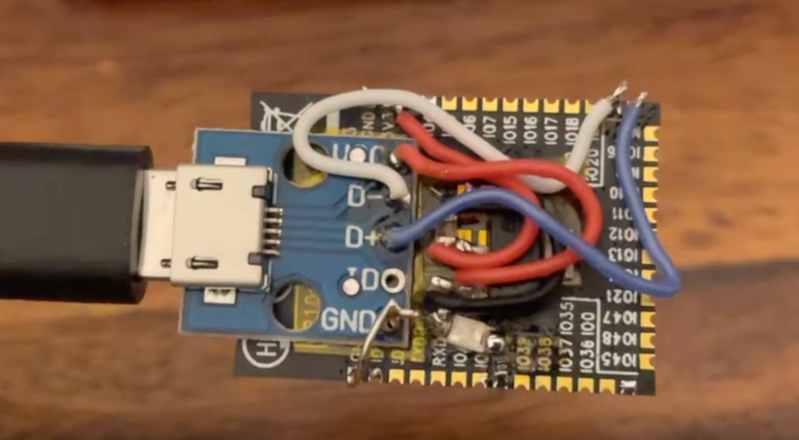
Building the circuit on a breadboard shows that this minimalist design works, but instead of building a tiny PCB to solder the ESP32 module to he attempted to build a sort of dead-bug support circuit on the back of the ESP32. This didn’t work particularly well so a tiny dev board was eventually created to host this small number of components. But with that, the ESP32 is up and running. These modules are small and compact enough that it’s actually possible to build an entire dev board setup inside a USB module for a Framework laptop, too.


checks datasheet
minimal circuit diagram supplied by manufacturer
hasn’t everyone done this already?
“A 3.3V regulator eliminates the need for many of the decoupling capacitors” – wait, what?
That doesn’t make much sense at all. Sure, you probably *could* skip most if not all decoupling in many circuits, but at the price of less stability & reliability (a.k.a. Muntzing : https://en.wikipedia.org/wiki/Muntzing )
“and the external oscillator support circuitry can also be eliminated when using the internal oscillator.”
Maybe you can, but what is the accuracy, tolerance and stability of the internal oscillator compared to external crystal/osc ? What are the implications for things that may | may not suffer when the system frequency deviates too far? Typically, a reliable USB link is a common example that might not be reliable when using internal (uncalibrated / uncompensated) oscillators.
I’d expect the same for RF. BT channels are pretty narrow, right?
So it may well be that this Muntzing seemingly “works” (sometimes? for a while?) at 25C / nominal voltage / sample-size 1 or a few. And that’s cool.
But just because something seemingly ‘works’ in a test setup, doesn’t really mean it works ‘for real’, reliably.
But yea, anyway, it IS kind’a cool that you can sometimes run a pretty complex MCU or SoC with nothing but a CR2032, or VBUS & Gnd from a USB cord, etc.
What I think they mean with ‘external oscillator’ is the optional 32KHz crystal that allows the ESP to keep proper time in deep sleep. The module they use already have a 40MHz crystal inside it that handles the USB and RF timing.
(Note that you can actually get accurate timings using USB without a crystal; you’d use the trick that USB links see a SOF packet exactly every one millisecond, and then train a PLL to use that as a base frequency. The ESP32-S3 doesn’t use that since it’s generally always coupled with an accurate 40MHz crystal, though.)
Ah, that makes sense, thanks!
I see now there’s a whole bunch of stuff underneath that tin can :)
In theory you are right in practice, for DIY projects using esp32s you only need 2 things: a) Voltage of around 3.0-3.6 volts and a resistor between EN and VCC (and maybe you can even skip the resistor by shorting them).
I’ve been running 12 ESP32 modules through out my apartment for 6 months with the exact setup that I just described. A cheap 220V AC to 3.3V DC regulator from HiLink and a single 10k resistor. That’s it, no decoupling capacitors, no common mode coils, no fuses, and no external circuitry at all. And guess what, it just works, so far I had no downtime, crashes or instability.
Of course I am out of spec, in theory the ESPs can just crap out at any time, and obviously I cannot sell these things because I broke a million regulatory rules. But so far so good, and I save a few milliAmps of power and space than using a more expensive ESP devboard with USB power.
It was the same story with Atmel MCUs, you just needed appropriate voltage nothing else for hobby use.
It’s a little deceiving.
Open up the schematic for what is in the ESP32 MODULE. There’s more than the IC in there. Decoupling caps are always a good idea since you are dealing with a radio that will have peak transmissions. They help to stabilize most voltage regulators. Very few can operate without external components, usually it’s only the very old regulators that also have a high quiescent current draw and a relatively high drop-out voltage.
Note that this is specifically about the ESP32-S3. The ‘classic’ ESP32 (without S, C or other letters behind it) does not support USB, so you’d still need an USB-to-serial chip or module.
Been there done that… but two years ago.
https://twitter.com/xorbit1/status/1430198690883411969
That messy board looks anything but minimalist.
I stopped watching when he started eliminating decoupling capacitors. This is terrible advice and shouldn’t be followed. Please note that decoupling in this context has nothing to do with filtering, which is a very welcome side effect. You *need* decoupling also when supplying devices with batteries. Decoupling means that if you drive for example a relay or a motor, or your hardware will simply start intensive calculations, the sudden spike in current draw will not travel back to the chip along the supply lines generating all sorts of potential problems, including spontaneous resets and other glitches. This is also valid in analog electronics; if you ever built an audio amplifier that squealed like a monkey although there was no input signal, the reason was certainly to be found in the lack, misplacement, and/or miscalculation of the decoupling capacitors, or even use of bad quality ones. Picture this: any small variation in the load driving should be contained by large value caps around the final stages, but they’re not there or are insufficient, so that the signal travels back through the supply lines to the input stages where it somehow reaches the signal input (imagine an input transistor base connected to the supply positive through a resistor, or a voltage divider on a opamp input); now the signal is being amplified and sent to the final stages, starting a self oscillation.
Removing decoupling capacitors is always wrong; please don’t follow such advice.
Interesting. Many thanks from this novice hobbyist!
The reason why this still works is that there are decoupling capacitors within the module. See a teardown here:
http://electronupdate.blogspot.com/2018/08/espressif-esp32-teardown.html
Remembers me the early days of those ESP01 back in August 2014: custom baud rate for the bootloader, 3.3v power supply, at commands, ftdi usb-serial.
When is the global esp8266 10y anniversary party will happen?
Using thin lacquer solderable wire would do a better job in this case….
If you’re looking for a _practical_ minimalist ESP32 board, Seeed Studio makes an ESP32-S3 and an ESP32-C3 which is smaller in width and length than the full-sized ESP32 dev modules. They are easy to solder to a PCB, and unlike the dev modules they include a USB-C connector, LiPo battery management, external high and low speed oscillators, and yes, even bypass capacitors.
The only downside is that you only get 11 I/O pins, but that’s enough for many projects. You also don’t get a PCB antenna and must use a u.Fl antenna (included), but that opens the door for using a better antenna that provides more range.
All this for about $3 more than the respective dev modules. That’s probably cheaper what it would cost me to buy (at low quantities) the USB-C connector, the voltage regulator, the oscillators, and all the “required” capacitors, and saves so much time when assembling the board.
There are knockoff Xiaos available as well with built in antenna and battery connectors that have 2 extra pins and are only slightly bigger by the width of the extra pins
You can’t just use any old ESP32 like this. You need to use the ones with built in USB.
Great minimalist demo….thanks. I will try one out, too. And i will also try an ESP8266.
PS…..please use plenty of extra flux. That’s the only reason your soldering is difficult. But thanks for the show.
This will only work on specific ESP32 boards that have USB built in. ESP8266 don’t have this.
This isn’t the same as a dev board with a USB socket, this is a specific model of ESP32.