[jgpeiro] is no slouch when it comes to building small, affordable oscilloscopes out of common microcontrollers. His most recent, based on an RP2040 with two channels that ran at 100 MSps, put it on the order of plenty of commercially-available oscilloscopes at this sample rate but at a fraction of the price. He wanted to improve on the design though, making a smaller unit with a greatly reduced bill-of-materials and with a more streamlined design, so he came up with this STM32-based oscilloscope.
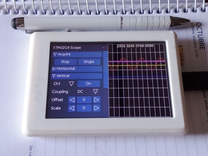
The goal of this project was to base as many of the functions around the built-in capabilities of the STM32 as possible, so in addition to the four input channels and two output channels running at 1 MHz, the microcontroller also drives a TFT display which has been limited to 20 frames per second to save processor power for other tasks. The microcontroller also has a number of built-in operational amplifiers which are used as programmable gain amplifiers, further reducing the amount of support circuitry needed on the PCB while at the same time greatly improving the scope’s capabilities.
In fact, the only parts of consequence outside of the STM32, the power supply, and the screen are the inclusion of two operational amplifiers included to protect the input channels from overvoltage events. It’s an impressive build in a small form factor, and we’d say the design goal of keeping the parts count low has been met as well. If you do need something a little faster though, his RP2040-based oscilloscope is definitely worth checking out.


looks good, all it needs is an i2c mode (I use my i2c bus monitor about 10 times more than my oscilloscope..) :-)
Yes, in future versions I can add some digital channels too
I often find that the real need is something that can decode and trigger from bus traffic, while showing the analog waveform of that bus traffic. If the bus is already working correctly, there’s no need to analyze. If the bus voltages are clearly out of spec, it’s apparent without decoding. But if the bus fails in a specific case, then hell yeah I would like a digital decoding of the analog waveform. It can even be a separate threshold circuit that feeds a digital input that is then decoded, but that threshold needs to be adjustable
Nice “yes we can” type of project but otherwise about as useful as cleaning toilet bowl with a chainsaw. I’m an embedded software developer and for me Rigol 1054Z is about 6 hours of work.
Funny you mention the Rigol. I have a cheap one at work and have found that it lacks the true intelligent design that separates the quality test equipment from the junk. If you look at it’s “measurement” functions, they sorely lack trustworthy repeatability and accuracy. I test a RMS value with my fluke 88 and it is nuts on everytime but with the Rigo, it seems more like it has rounding errors and is more of an approximate guess. I would much rather have a cheap analog scope any day of the week over a cheap Rigol scope.
That’s because it is simply taken from the sampled data, which is probably only 8-bit unless the high-resolution mode is turned on (where it should be 12-bit, I think). So yeah, voltage measurements are pretty rough.
Moreover, 1054Z only calculates measurement functions from the screen data, which has been downsampled. This causes measured values to change when you zoom in.
There are better alternatives with similar price like Siglent SDS1xxx.
This is a very high-quality project, and the “mega-fantastic” article (translated into English using ChatGPT) is a fun read. Like a cross between Don Lancaster and J. Peterman.
No offense, but do you also go to gardening sites and bitterly complain that they didn’t buy all their produce at the supermarket?
Also, it’s not just about this particular oscilloscope project. It’s a good example of how to design a microcontroller project, and how to present that design to other makers.
So, a lot more useful than “cleaning toilet bowl with a chainsaw”. It’s just a good example of what a Hackaday article should be.
I agree it’s easy to rip someone’s else’s design .. show your version before you start barking
Looks like a job well done. Congrats.
Thank you
For all of the time and effort, as well as popular demand, *why not go for an ESP32-S2 variant (WROOM or ROVER)?
The ESP32s have (really) terrible ADCs. It also lacks the integrated op-amps, if I am not mistaken, which OP used.
Definetely possible to use ESP32s as the brain, but the BOM would increase a lot.
Goal from OP was to minimize the BOM, and using as many built-in resources led to the selection of STM32.
It doesn’t have the onboard peripherals of the STM. Heck, it doesn’t even have an accurate ADC.
Yes, as wibble mentioned, STM32 has multiple ADCs, multiple DACs, PGAs… I think ESP32-S2 is more limited in terms of analog peripherials.
I love the “mega-fantastic” writing style – it actually kept me engaged enough to read the whole article and helped understand what was going on. Makes the project sound REALLY, REALLY GOOD as well.
Glad to hear it. I didn’t know if people would like it or not, but now I see that it was a good decision to leave it like that.
Thank you for the write up on the project. Non – native speakers may find it hard to understand the writing . Please use simpler language so that more of us can understand.
It was already in my intention to simplify the writing a bit, I don’t speak English natively either and I don’t need chatGPT to “create a novel” where I dont know 5% of the words, it is enough for me to help me just a little so that it is well explained.
I realized that I was drifting more the longer the conversation was. I saw it late and I preferred to leave the note at the end rather than repeat it again.
…Maybe next time I will ask to “translate as if it were a datasheet”…
I sort of do like the project, and you clearly put a lot of effort in the user interface, but as a project it severely lacks a frontend on the hardware side.
This is quite a shame. I think this could be a viable product as a combination of development kit and usable product in itself, but that can not be it without a frontend.
A long time ago I had a peek at the DSO nano project. It’s a cumbersome user interface on a small screen and it’s price has risen to close to a normal benchtop scope.
Things like the DSO138 from Jyetech have a very simple but usable frontend (with TL071 and 74HC40xx multiplexers) but they lack on the software side. Triggering and buffering is atrocious and it has a very small LCD, although that may be justified for their price point. It’s also only partly open sourced and more difficult to modify or extend into something useful instead of just the toy it is now.
It’s hard make something like this viable as a kit, when you can buy a full blown benchtop scope for EUR250.
I hope I did not focus too much on the negative side.
It would be nice to see (some other?) person take this up and add the front end, (and then yet again maybe integrate with something like OpenHantek).
I had a DSO138 and I love its schematic simplicity. Even I thought that it deserves a little bit better fw and I built it ( https://github.com/jgpeiro/dso138 ), but I loved its HW so much I decided to try to build oscilloscopes by myself…
After some research I thought I can build a 2-ch 100MSps with a RP2040, and It worked, but the BOM was too big, plenty on improvements everywhere, and there also was the semiconductor shortage…So after that I tried a different approach, less BW, and with that I can move some parts to the MCU and increase the number of channels without increasing the BOM…Even I removed the negative power supply, so of course it lacks of a real frontend…
It accomplishes exactly what it was designed for: +-10V, 1MHz, 10K of input impedance, and it allows me to develop the firmware side and play some time with it
Does it have an XY mode?
It seems most all digital scopes omit this capability
No, but it can be added
Pretty neat. But 100Msps is pretty low for an oscilloscope. May give you only about 10 or 20 MHz analog bandwidth depending on how steep your nyquist filters are. Barely enough to display a 1-2MHz square wave with sharp edges.I think at least 250Msps or preferably over 400Msps will improve its use. I’m thinking of designing one myself, but high performance ADCs are very expensive starting from about $50 for single channel ones and a lot more for multi channel ones. I still have a Red Pitaya which has a 125MS/s sampling rate. Marginally better. I might play with that one again.
No, you have turned it around.
100Msps is quite impressive for a small and cheap uC that also has to handle a GUI and other tasks, and you should have stopped there.
There is plenty more capable hadware around, but those have other goals. If you feel a need to feel impressed by raw specifications, you can have a look at this video from Shari-Harri-Shark from The Signal Pathof this oscilloscope: https://www.youtube.com/watch?v=8WNuGUQStq8
No, you have turned it around.
While 100Msps would be impressive for a small MCU, his STM32 certainly isn’t a small one and only his the RP2040 samples at 100Msps, not his STM32. Comparing a 1MHz oscilloscope with a 25Gsps one is comparing apples to space shuttles.
I like his GUI, but it’s simply not practical for me.
I really don’t care whether it’s 1Msps, 10Msps or 100Msps, It’s just a nice project and I like it no matter whether it’s an STM32 or a RP2040.. You started complaining about performance, not me. Also, nobody here cares whether it is practical for you or not, so please go complain somewhere else.
Well done!
His goal was minimum bom, because of that, imo, it’s a little slow to control the scope through the GUI. I would want the most used knobs physical, like volts, time, trigger, run/stop, etc. Maybe add an option, another pcb with small mpu that takes the input encoders, switches, pots, etc and encodes it to SPI or i2c over to the main mpu.
Thanks for sharing.
I’m willing to buy (for School project purposes). I would like to contact the owner/maker. Anybody knows?