Some people hate to revisit projects that are done and dusted. We get that; it’s a little like reading a book you’ve already read when there are so many others to choose from. But rereading a book sometimes reveals subtle nuances you missed the first time around, and revisiting projects can be much the same, as with this new and improved Doppler radar speed sensor.
We seem to have been remiss in writing up [Limpkin]’s last go-around with the CDM324 microwave module, a 24-GHz transceiver that you can pick up on the cheap from the usual sources, but we’ve featured this handy little module in plenty of other projects. [Limpkin]’s current project uses the same module to create a Doppler speed sensor, but with a little more sophistication all around. Whereas the original used a simple comparator to output a square wave that’s proportional to the Doppler shift and displayed the speed on a simple terminal session, version two takes a different tack.
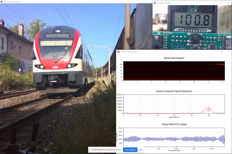
First, [Limpkin] opted to implement the whole sensor in hardware. The front end is quite different — an op-amp with 84 dB of gain followed by an automatic gain control (AGC) stage built from a MAX9814 microphone preamp. Extraction of the speed from the module output is left to an STM32F301 running an FFT algorithm on the signal coming out of the analog circuit, which essentially picks out the biggest peak in the spectrum and calculates the Doppler shift from that, displaying the results on an LCD display.
Of course, as a [Limpkin] project, there’s a lot more to it than just that. The write-up is very detailed, going down a few enjoyable rabbit holes like characterizing the amplification chain and diving into the details of Johnson-Nyquist noise to chase down stray oscillations. There’s some great stuff here, and it’s well worth a deep read; there’s also the video below that lets you see (and hear) what’s going on.


The module is CDM324, not CM324. I googled it and was just finding out about a Panamanian airline’s flight.
It’s really interesting how the audio representation of the doppler data of the train passing sounds just like the actual sound of a train passing.
Thanks for the right part number. “The Signal Path” youtube channel did a tear-down of the CDM324 module about 5 years ago: worth a watch:
https://www.youtube.com/watch?v=5vqSX40seqA
That’s probably because you also hear a doppler shift when the vehicle comes at you.
Yeah, i also wondered why it sounded like that, like if audio component was leaking inside the signal. My first thought was it could be because of the space between 2 train cars making the measured distance increasing then decreasing, but i would expect the sound going alternatively up and down. Then i realized it’s probably because of the intermittent reflection on the bogies/wheelsets, whose are producing the rolling sound at obvisouly the same time.
I’m also wondering if the speed measurment is reliable, since for cars examples, the speed indication (matchin the heard sound) shows speed starting from 0 and continously increasing, when the cars are more looking like having a constant speed and not accelerating. So it seems that real instant speed can’t be inferred.
I believe that the zero speed reading is because the cars are first showing up on the spectrogram when they are near their closest point to the device: ie neither getting closer to or farther from the mic.
Actually, upon further thought, I think that we only see half of the computed spectrogram, either the positive or negative speed.
If an object moves at a steady speed along a line past (but not through) an observer then:
A: first, there will be some time where it is getting closer to the observer (pitch Dopplered up)
B: after it passes, there will be some time where it is moving away from the observer (pitch Dopplered down). But,
C: in between, there will be some moment where it is neither getting closer to or further from the observer, and therefore have no Doppler shift (calculated speed of zero)
True even if the the car is moving at the same speedometer speed the entire time!
I believe that the zero speed reading is because the cars are first showing up on the spectrogram when they are near their closest point to the device: ie neither getting closer to or farther from the mic.
Actually, upon further thought, I think that we only see half of the computed spectrogram, either the positive or negative speed.