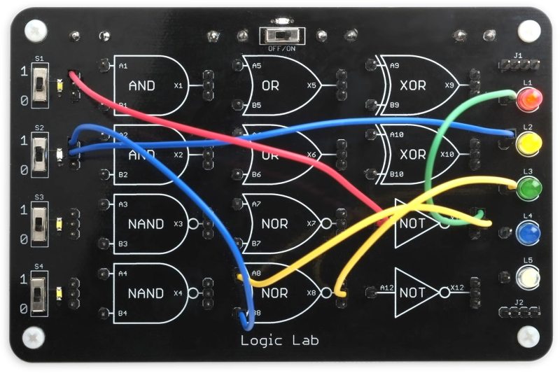
The digital world offers many advantages over its analog relatives, the use of boolean logic among them. Some of the functions, like NOT, OR, and AND are fairly straightforward and line up nicely with their linguistic counterparts. Others are more elusive, like XOR and NAND. For those just getting their start in digital logic, this teaching tool allows different logic gates to be wired together with patch cables.
While [David] first thought to use 74-series logic circuits directly, a much more versatile solution was to use configurable custom logic — a feature found in AVR DA-series microcontrollers that allows for the creation of custom logic circuits without the need for external hardware or complex programming. He went with an ATmega4809 which is capable of supporting twelve gates which are depicted graphically on the board, where the patch cables can be connected between inputs and outputs from a set of switches on the left to another set of LEDs on the right. The microcontroller continually polls for connections, applies the correct logic via a lookup table, and lights the appropriate LED.
Even with only twelve gates, the amount of real-world analogs that can be created with this teaching tool are numerous and varied, from simple things like displaying traffic light patterns in the correct order to implementing a binary adder. It’s an excellent way to get started in digital logic or understanding gates, and much simpler than dealing with 74-series chips on a breadboard like many of us might have done, but those logic chips can be powerful tools to have on hand even in the modern world of microcontrollers.


Beautiful, great tool for teaching.
Non, no, no. Sorry but [David] does not use the logic gates in the AVR microcontroller. There are to few gates
[David] says
“However, I then thought about using the Configurable Custom Logic (CCL) in the AVR DA-series microcontrollers, which allows you to configure three-input gates that work independently of the processor. The advantage would be that you could reconfigure the selection of gates in software, without needing to resolder the board. However, even the largest 64-pin devices only provide six logic gates, and in the 48-pin packages it seems that only five of these are actually available on I/O pins.
My final design used an ATmega4809 or AVR128DA48 microcontroller, but simulating the gates by polling the inputs, and setting the outputs accordingly, using truth tables stored in the program.”
and concludes with
“Even though the logic gates are simulated using a microcontroller,”
If it’s not using actual gates, which might catch hardware errors that a simple simulator like this wouldn’t, then I’m not sure what the advantage over a full logic simulator, which would have far fewer limits on complexity. And also, I don’t see even the simplest flip-flop here, although yes, you could build an SR or D flip-flop with the gates provided. And also, trying to construct a simple ring oscillator out of three inverters and some resistors and capacitors simply would not work. Seems like the student would hit the limits pretty quickly. I can see this being used in a classroom, though, where the very beginnings of digital logic could be taught to many students over time, though.
I am baffled that it needs a microcontroller to do this, but we all use what we have in the drawer …
– just 6 HC chips would do the same job and reflect the real circuitry.
Or an simple nano many of us have plus 3 shift registers for inputs and two 595 shift registers for Outputs would do the same.
Why not do it using an FPGA?
Or really, why not just use those 74HC chips? Most of the work on this is in packaging it, and I don’t see how hooking wires up from header pins to a microcontroller is any improvement at all over hooking them up to a few ten-cent logic chips.
Simulating logic with a µC this way has another drawback: it doesn’t work like 74xx/4xxx logic, it’s more like asynchronous clocked logic with unpredictable propagation delay. It might behave funny with feedback loops (latches) and circuits that exploit propagation delay (XOR frequency doubler). That could possibly be fixed in software, if you find a way to read or write all ports at once, except for the clocked part.
I suspect the microcontroller is cheaper. :-) And it’s one chip instead of five or six!
If it is for educational purposes. Burkhard Kainka did a nice kit
– no wires , only jumpers, so it is a DPAA – Desk Programmable Analog Array
https://www.amazon.co.uk/Electronics-Experimentation-System-Programmable-Analog/dp/B0B5PDWM3X
And the same hardware DPAA hardware can be used for digital basics – see the description in German and the translation into English here
https://b-kainka.de/Experimente/Digitaltechnik.htm
I think there’s something to be said for the tactile physicality of this as a teaching tool. And the very limitations of it make it simpler for a novice to grasp. But you can do so much more with even a novice-targeted simulator. I will say, though, it reminded me of the DEC Computer Lab I had for a while in 1971. DEC loaned one to my school and the computer club sponsor let me take it home for Christmas break. I learned so much about the basics of digital logic as a 14 year old. It was a foundation for the next fifty years working with computers.
My first impression of the Title Photo, made me think this was going to be about Lab-Volt trainers.
https://labvolt.festo.com/solutions/2_electronics/98-91000-00_facet_electronics_training_system
Back in my day we just used actual logic ICs. And wires stuck into little springs instead of 0.1″ headers. Uphill in the snow both ways with ever-so-stylish onions on our belts.
Reminds me of the Hackmanji game that Ben Heck made.
Thanks for the 2018 link to that 6502 CPU made of 74-series chips. It’s lovely, and I want one.