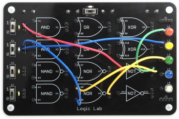
The digital world offers many advantages over its analog relatives, the use of boolean logic among them. Some of the functions, like NOT, OR, and AND are fairly straightforward and line up nicely with their linguistic counterparts. Others are more elusive, like XOR and NAND. For those just getting their start in digital logic, this teaching tool allows different logic gates to be wired together with patch cables.
While [David] first thought to use 74-series logic circuits directly, a much more versatile solution was to use configurable custom logic — a feature found in AVR DA-series microcontrollers that allows for the creation of custom logic circuits without the need for external hardware or complex programming. He went with an ATmega4809 which is capable of supporting twelve gates which are depicted graphically on the board, where the patch cables can be connected between inputs and outputs from a set of switches on the left to another set of LEDs on the right. The microcontroller continually polls for connections, applies the correct logic via a lookup table, and lights the appropriate LED.
Even with only twelve gates, the amount of real-world analogs that can be created with this teaching tool are numerous and varied, from simple things like displaying traffic light patterns in the correct order to implementing a binary adder. It’s an excellent way to get started in digital logic or understanding gates, and much simpler than dealing with 74-series chips on a breadboard like many of us might have done, but those logic chips can be powerful tools to have on hand even in the modern world of microcontrollers.


