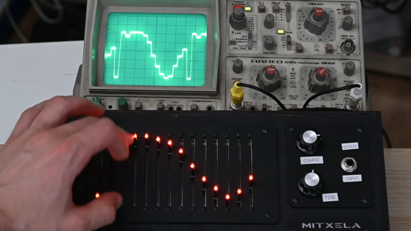
Usually, an oscilloscope lets you visualize what a signal looks like. [Mitxela]’s reverse oscilloscope lets you set what you want an audio waveform to look like, and it will produce it. You can see the box in the video below.
According to [Mitxela] part of the difficulty in building something like this is making the controls manageable for mere mortals. We really like the slider approach, which seems pretty obvious, but some other controls are a bit more subtle. For example, the interpolation control can create a squarish wave or a smooth waveform, or anything in between.
This is sort of an artistic take on an arbitrary waveform generator but with a discrete-panel user interface. The device contains a Teensy, a Raspberry PI Pico, a 16-bit ADC, and an external DAC. The Pico is little more than an I/O controller, reading the user interface and transmitting it on a serial port.
The outside construction looks excellent (we assume the tape is temporary). The inside is a bit messier, but still nicely done. There are many photos of the construction and details of problems along the way with 12-bit ADCs and power supply experiments.
Of course, if you don’t need the user interface, you can go crazy with waveform generation. We did our own similar project, but you could draw your waveforms on the PC instead of sliders.


Isnt this called a waveform generator ?
Hell yes. And for years, analog synth companies have been making very similar devices.
https://www.modulargrid.net/e/sputnik-modular-dual-multisegment-function-generator
https://www.modulargrid.net/e/verbos-electronics-voltage-multistage
Not to mention a long list of analog sequencers with sliders that can be run at higher speeds to make arbitrary waveforms.
https://www.modulargrid.net/e/stg-soundlabs-graphic-sequencer
https://www.modulargrid.net/e/detroit-underground-du-seq
https://www.modulargrid.net/e/medic-modules-ekg-
https://www.modulargrid.net/e/gmsn-pure-sequencer
and on and on.
In the synthesizer world this is called a sequencer if you add a separate trigger output generating a pulse for each next step. I once made one with 40 knobs to be used as a midi controller, using a blue pill only. But of course there was midi out, no analog.
And of course you could use a 555 (and a binary counter chip and a 4051 analog switch or two)
Mitxela’s handle is misspelled 2 times in this article :D
LOL, fixed.
There’s owt kinds of elpoep in this world: those who periodically read things backwards, and those who don’t.
Here is another take on this topic I made 10 years ago… works with oldschool arduino
https://youtu.be/Rv29Vwd8wTc?si=K4c1NxYwySdStqNh
In the test equipment world, it is called an Arbitrary Waveform Generator – You get to define the waveform and it repetitively spits it out at varying speeds. In the Syth world, crudely, its a sequencer.
Interesting interface though :-)
I would have thought that a touch screen display and a stylus would make a more elegant interface… probably simpler too.
Oh, the hours I wasted with one of these as a child! That was on a Mac, so no nice physical controls.
Have often wondered about making a physical version, this is nice.
It’s called an arbitrary waveform generator. Some Oscopes have one built in.
Doesn’t the Fairlight CMI have a mode where you could draw a waveform on the CRT screen with a lightpen and it would then play it as a sample?
I have a few early VCR tuner banks of fine “tunable” pots used to set the channels manually to fit the limited number of slots to record from. There are 12 or 14 thumbwheel pots that would make a fine-tunable as a note sequencer, they are quite small. I’ve cut into one to make 8 steps but never got around to the rest. Those pot banks are now extinct but a few junk VCR’s are still out there. Slide pots might be fun to play with but, tuned notes are harder to get when the slide pot covers 5 octaves.
Cool. How about if the interface was a reverse spectrum analyzer with each slider representing each ‘A’ note frequency (440Hz, 880Hz, etc). You could add 7 push buttons to select different notes/chords or just have a few dozen sliders (about 7 sliders x 7 notes). Instead of sliders you could just have analog keyboard switches.
You’re describing an additive synth, if I’m not mistaken :)
That’s basically what’s done with varying degrees of “Spectrum points” depending on the synth, some even allow modulating of those points, some only in the Y axis, others in X, Y and “width” of the spectrum range.
In fact, that’s basically what an organ with drawbars is, as an example of a more limited and usually less sophisticated “additive synthesis” based musical instrument.
You guys are nerds lol just wanted to say that, funny thing is the comments are better than the article, thank you for the laugh
When I saw the title, it reminded me of an idea I read in the 80’s where someone had a light sensor and control circuit that drove the Y channel of an oscilloscope.
You cut a piece of card to your desired waveform shape and the circuit arranged that the oscilloscope beam tracked the upper edge of your card. The output of the circuit was your desired waveform.
You controlled the frequency manually by tweaking the timebase.
I guess there was a loud click on every cycle as the beam flew back to the beginning but it was a neat idea for limited hardware.