A signal generator that can produce the usual sine, square, and triangle waves is handy and has been a staple of electronic benches for decades. Being able to craft custom signals opens up new horizons, but historically, these instruments were expensive. The price has come down, though, and [Rishin Goswami] made a 5 MHz 8-bit signal generator with 131K data points of arbitrary waveform for a low price: about $20. If you want to spend a bit more, you can improve the output DAC and op amps, but even that should cost well under $100, all in.
This is one of those projects that seems easy until you start digging into it. For example, storing some points and generating signals using any microcontroller isn’t a big deal. But minimizing jitter and maximizing speed with a conventional processor is difficult. That’s why [Rishin] uses a Raspberry Pi Pico. The programmable I/O units are perfect for generating waveform data fast and reliably. You can see the project go through its paces in the video below.
The Pi streams data to an 8-bit DAC. However, it would be easy to improve resolution with a different converter. The DAC0808 also limits the instrument’s sample rate. The processor could likely go much faster if it had a DAC accommodating higher speeds.
This is just a proof-of-concept, so don’t expect fancy GUIs or the ability to import spreadsheets. You control the device from a command-line-like interface. Still, a good example of how to take advantage of the Pi’s hardware. We took a shot at a similar device nearly a decade ago. Those programmable I/O blocks are finding uses in some surprising applications.


The project I work on at work has need for a multi-channel signal generator. Our standard product has 64 sensors reporting analog data with mid-to-high end precision and accuracy requirements, including tight accuracy in event time reporting. These sensors need DC to 20-30 kHz bandwidth. Any real system test environment would allow feeding all those sensors with well-defined test signal patterns.
We of course cannot afford to buy, and importantly, synchronize 64 channels worth of signal generators…
We are ready willing and able to build an array of signal generators using microcontrollers (PJRC Teensy: solid product) with audio peripherals. We have been using Teensy 3.2 (single 12-bit DAC) and are moving up to Teensy 4.0/4.1 with PT8211 stereo DACs. I2S is efficient and well supported. The PT8211 is a plain DAC, so it supports DC-to-high-frequencies. PT8211 is a fairly old design and I am concerned that we would need to find a replacement.
The trouble is that modern I2S DACs are all “capacitorless” now, with output stages designed to enforce AC coupling, and I cannot find a part that allows disabling that feedback path.
So this is a note to manufacturers: There is a (possibly small) market for I2S DACs which allow one to disable the digital “AC coupling” feature.
What if you just add the DC component yourself with a digitpot and actual capacitor?
Our application depends on measuring differential signals, collecting and analyzing the difference between a rapidly time varying application signal (30-25 kHz) and a slowly time varying “DC” offset (0.0001-0.1 Hz). We thought about using a separate source for the slowly varying signal and the higher frequency signal as you suggest. What turned us off to that option is that the high pass filtering of the higher frequency signal would inevitably affect the accuracy of our testing. We could need to perform a fair amount of analysis and testing to verify that splitting the test signal into separate LF and HF components can accurately validate our production system.
I have also looked into straight up SPI DACs. I could either build an SPI-based audio driver to fit in the existing Teensy/Arduino infrastructure or just go straight into bare metal (which is what we are doing with the existing Teensy 3.2, driving its on-chip DAC directly).
Our production code and existing Teensy 3.2 signal generator exist, are already bare-metal, and it would be possible without too much coding to fix up an SPI layer. We were just hoping to get away with the existing Teensy/audio world: Our bread and butter is not writing test code but ensuring our production system meets spec. Like everyone else in the world, we are already overloaded with schedules, management, etc…. :-)
131072 is 128K, don’t care what SI says
Si is right you are wrong. It really is that simple. I do not give a hoot (whatever that even is) about your misconception, even though it is as common as it is.
Nah. Computers naturally work in powers of 2, and saying things like “65K” or “131K” just obscures what’s really going on. So SI swans in with their ten-centric fixation, and they’re just “right”? They’re a standards committee so they can say whatever they like, doesn’t necessarily make them *right*
If you use K to mean 1024, you are being inconsistent with essentially every other use of it. It would be neater to say Ki, like in kibibytes.
But you have no problem with the 5MHz sample rate, or should it really be expressed as 4.7683715 Mhz?
There is really zero ground for any discussion on this topic.
If you continue, it only confirms your ignorance.
I assume you also still use banana units to measure lengths, weights and other things.
Go ahead if you like, but don’t bother the rest of the world with that nonsense.
Sorry, but using non-base-2 units when dealing with memory is simply inviting more errors. In the end it boils down to what is practical and base-10 simply isn’t when talking about cascaded logical gates.
No it’s not.
The confusion is already here.
Look at HDD and SSD manufactures that use base10 and base2 units as it pleases them.
Also look at B versus b. A common convention is to use B for Bytes, and b for bits, but there is no consensus. Also look at uSD cards. The size they actually have is just a guess.
Therefore the only way to get rid of confusion is to adhere to existing standards. And the best standard I know for binary based units is: https://en.wikipedia.org/wiki/Binary_prefix
And the majority of people ignoring those only prolongs the confusion.
Another pet peeve is the “m” versus “M”. Just yesterday I read a comment on youtube from someone that need a whole sentence after his 50mHz that he really meant 50 milli Hz instead of 50 Mega Hz.
> base-10 simply isn’t when talking about cascaded logical gates.
Most of the time, nobody cares about how many logic gates are cascaded. They just want to know how much memory they have in easy to understand units. Plenty of media, such as tapes, floppies and hard drives don’t even have cascaded logical gates. Other devices may have gates, but still be arranged in different numbers. I had a computer with 12K of RAM, which is not a power of two.
To be fair, the SI prefix for kilo (1000) is the lower case ‘k’, so one might co-opt ‘K’ to mean 1024. You might assume at least a few people will figure out from context what you actually mean.
That won’t help you with ‘M’ vs. ‘m’ though.
Meh, it’s a neat project, and there surely are a bunch of hairy details to figure out. It is certainly a few steps above “average arduino level programming”, but it’s not that impressive either. I think you can quite easily do circular DMA with an STM32 at 10Msps with 16 bit output. With a TTL buffer on the output (Power from a Reference voltage) R-2R network (home sorted resistors) I guess you can get a quite good accuracy. Not 16 bit, but you can use a few bits for amplitude control, so you only need a few coarse steps in hardware for a decent amplitude range. But the PIO of the rp2040 may be a valuable peripheral for reliable output too.
It’s a project I think of building myself every now and then. One of the things I thought about is to have two or more sample buffers and then pre-calculate the samples in a buffer switch between those buffers during either amplitude or frequency change, so the transition seems seamless. This may also need some tricky programming to get right.
His rationale that: “Even the relatively cheaper ones with specifications like 150MS/s, 50mhz (Red: I think he means 20MHz here), 14-bit cost above $300.” is not true. You sure pay though the nose (or arse?) for a Keithley, R&S or Siglent, but the Chinese FG’s such as “Juntek” “Feeltech” and clones or rebands are quite affordable. Even Owon also has an affordable FG with the DGE2035 which costs just EUR135, and that is inclusive a quite big TFT lcd and nice box and front panels with buttons. It’s hard to DIY something for that price.
Doing 100Msps is also ambitious for an uC, but it is easily achievable with a small FPGA such as all the examples shown above do.
Owon now does a 70MHz/300Msps/14-bit AWG. Unfortunately the specs are kind of rough and there is no 10MHz reference input. But hey, it is $179.99 on Amazon – maybe less on AliExpress:
OWON DGE2070 Arbitrary Waveform Generator Dual-Channel 70 MHz Generator 14 Bits Vertical Resolution with 3.6” LCD 5.0 5.0 out of 5 stars 3 ratings $179.99
https://www.amazon.com/Arbitrary-Waveform-Generator-Dual-Channel-Resolution/dp/B0BPY2MJDF/
Visit the Abestop Store
https://www.amazon.com/stores/Abestop/page/D9BDB4A5-B3F8-44DB-81CE-EA8C5BB0E535?ref_=ast_bln
Someone needs to hack these cheap OWON AWGs to accept a GNSS disciplined VC Clock Generator based on the Skyworks Solutions Inc. Si571.
https://www.mouser.com/c/passive-components/frequency-control-timing-devices/oscillators/programmable-oscillators/?series=Si571
EEVBlog Forum has a thread on the Owon DGE2035 35MHz AWG:
https://www.eevblog.com/forum/testgear/owon-dge2035-dge2070/
Kerry Wong did a review/teardown of the OWON DGE2070 70MHz AWG:
https://www.youtube.com/watch?v=wnn7E6sbsQA
https://www.youtube.com/watch?v=wnn7E6sbsQA
It’s a cool project, but AWGs are not expensive anymore. They might even be built into your scope.
If not, they have plenty for under $110, and probably crappier ones with similar specs as this for even less.
AWG’s may be relatively cheap these days, but that does not mean a project like this is totally without merit. First there are plenty of people doing such things just for shits and giggles. But there are also people like “DeveloperLen” (See first comment here) who is looking for a way to simulate 64 sensors simultaneously. With something as cheap, small and compact like this it’s both doable and affordable to put a bunch of things like this in an Euro rack.
We might be able to get away with inexpensive signal generators if not for the requirement of synchronizing them very very tightly. Time measurement accuracy is an imporant aspect of our production system.
ST has a few application notes concerning combining DDS and DMA I think that combination is better than the PIO in this RP2040, but I am not sure. I have also seen several function generator projects with this configuration.
Keeping multiple function generators synchronized is also quite doable. You can for example use a single master clock for all function generators. If you build Euro rack modules, you can probably put 4 to 8 function generators on a single PCB, and you can fit quite a lot of PCB’s in an Euro rack, and then distribute the master clock signal through the backplane. The master clock can be a single TCXO or OCXO (you can start experimenting with cheap second hand oscillators from Ali or Ebay.) It’s quite common to have a master clock generator in high-end measurement equipment. Frequency counters for example often have a 10MHz input on the back if you can provide a better time standard than the thing has internally. The best would be Rubidium or GPSDO these days. Just pick what you need. The master clock generator can also be a separate module in your Euro rack, so you can easily replace it with another (better) one later.
Apart from the master clock you can also add a “zero crossing” or other synchronization signal and integrate that with the function generator firmware.
Addition:
You can also distribute the master clock to your measurement device, or the other way around: use the clock of your measurement device as the master clock for the signal generators. That way the whole system will always be synchronized without any clock drift.
That is nice for the lab and some measurements, but not in real life.
You can also introduce deliberate and defined clock drift between parts of your system by using high resolution DDS chips. I bought a few AD9850 modules from Ebay some 10 years ago and these are quite impressive devices that can generate a clock with a quite high resolution Output is up to about 40Mhz and with a 125MHz reference clock it has a 30mHz (Yes, milli Hz) resolution. They have a 32bit accumulator, and resolution scales with input frequency. There are better DDS IC’s but those also cost more. These modules also have a 5th order LCR filter on board which makes them easy to use and they can also produce a quite clean sine wave output.
Good points all.
For the production system, ee have a set of techniques for measuring clock rate and drift with excellent precision and accuracy. It’s been working well since completing prototyping. (The specifics are TLDR and are almost certainly proprietary… :-) )
That said, for the system test setup I wish to build, it’s entirely OK to let one device produce a master clock, then let implement rate adjustment in the individual signal generators disciplined by that central source. For now I’m using Teensy 4.1 with PT8211 stereo DAC. The Teensy is based on a 600 MHz NXP RT1062 microcontroller, and is a great little board. In the final analysis, we’re following the Eurorack model but with off-the-shelf parts.
We have not settled on a specific mechanism for clock synchronization. The NXP RT1062 uses a now classical PLL clock chain, so we might be able to dynamically adjust the PLL parameters (one “count” at a time for stability) to simulate an externally disciplined clock. An alternative that would not totally break our test validity would be to perform an occasional increase or decrease of the PDB counter limit to advance or retard sample production as needed.
We are trying to use existing hardware as much as possible… I have gotten significant pushback on even a few channels’ worth of test setup.
I’m an electrical engineer with a circuits background and I can’t remember the last time I needed or wanted an arbitrary waveform generator.
Im a dude who makes stuff and Ive bought two in the last year.
one is being used in an asymmetric alternating current electroplating cell
and the other is being used in a dry electropolisher.
As an electrical engineer you could probably duct tape a few transistors together and manage my usecases but as a dude who makes stuff I can drop less than $200 on amazon and make due.
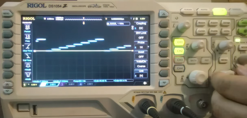
One fun and simple application for a two channel function generator is to make a transistor curve tracer out of it. For example, use one channel as a 6 level staircase signal, and the other as a triangle with 6 times the frequency. add a few resistors and an oscilloscope in the mix and you’re almost ready.
You may also use public transportation, but that does not mean that private cars have no use. It’s just a silly line of thought.
Speaking of silly, I said “arbitrary waveform generator”. I don’t consider a triangle generator (which indeed is quite useful) to be an “arbitrary” waveform generator. And you don’t even need a triangle generator for a home made transistor curve tracer … a half sine wave derived from the line voltage works just fine.