Usually, when you want a servo motor, you simply buy one already made. But if you need something unusual, you can turn any DC motor into a custom servo you can control just like [Dejan] did. You can watch a video of the process below.
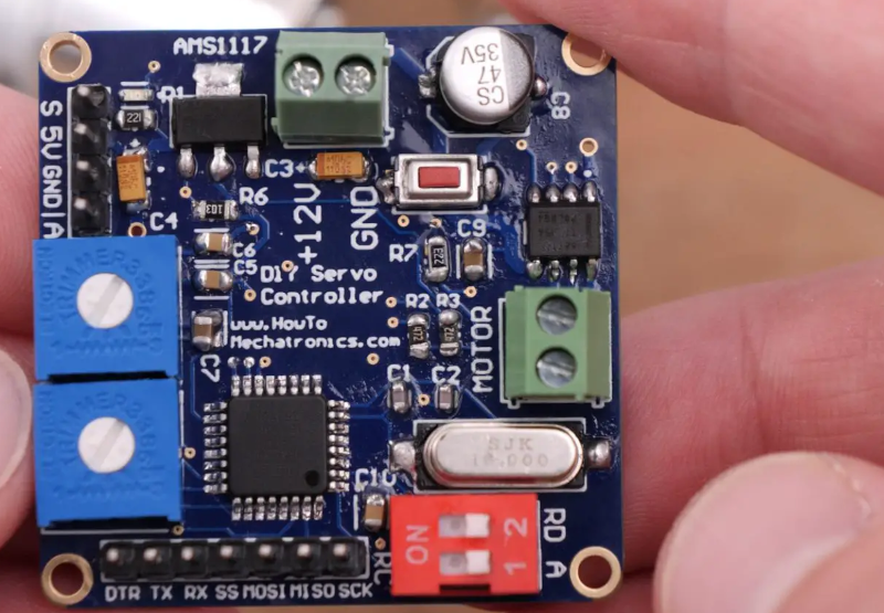
The custom servo can tune the endpoints, the center point, and the sensitivity. It also can be set to handle continuous rotation. A 12-bit encoder tells the microcontroller where the motor is and the output drivers can handle over 3 A of motor current. The microprocessor is a tried-and-true ATmega328. [Dejan] wanted to make the board as small as possible, and we think 40 mm square isn’t bad at all. There is also a 3D printed gearbox and housing. Overall, a very well-done project.
The motor control uses a PID algorithm. Potentiometers set the end range and sensitivity. A push button allows resetting the center position. DIP switches control the mode. The video shows a computer and an RC controller setting the position of the motors.
We have, of course, seen many variations on this idea. We’ve also seen servos rebuilt for better performance.


Very nice project overall, but that soldering… Ugghhh…
You are never allowed to look at my soldering. :P
Needs more flux….
Trying out the new comment boxes?
Yep ….. now testing after 1/2 pint of Dead Rat Cider …..
…. definitely improved.
Darn. I was hoping to see an actual general-purpose servomotor.
This is just a replacement driver for a hobby-type PWM servo.
It’s *really* time to drop brushed DC motors. BLDC is just as cheap to make, more reliable, less noisy, and the servo electronics to drive them are not really any more expensive.
(note to HaD: this new comment interface is awful)
I think this might be the prototype HaD comment against which all other comments can be measured.
1: Dismissal of project as too basic/uninteresting.
2: Random borderline related opinion presented as undeniable fact.
3: Moan about the site itself.
Just outstanding stuff, absolutely captures the negativity of the typical HaD comment.
4. It’s also factually wrong, just try to find a low-speed position control BLDC servo of any kind for less than a few hundred dollars each.
The TMC6300 can handle 11V, 2A per phase, is cheaper than the DRV8871 driver used in this project. You’ll need to add a few pins for the motor winding & sensor wires, but the rest of the BOM is pretty much the same, so costs will be similar. Though you’d be smart to replace the AMS position sensor: It’s OK here, but really limits it to limited angle hobby servo applications.
The TMC3600 module from Sparkfun requires “six PWM channels to fully control one motor” for some reason. That’s a big limitation, although the chip itself is just a straight up three phase driver. The DRV chip is far easier to use – just two PWM inputs.
What is wrong with that sensor? Isn’t it 12 bit resolution.
Dude, even the lowly ‘328P used here has 6 PWM outputs. That’s not a very high bar. And of course the DRV chip requires only two PWM signals. It only controls one phase!
Nico: That sensor is explicitly designed for use in applications that use less than a single turn. It has an overlap/hysteresis/deadband region at the end of travel. If used in a continuous rotation scheme that must be calibrated out and specially handled. There are better solutions.
Got a good laugh out of your comment, thx!
Why can’t I press Enter key in the comment box?
This is awful.
It’s worse than it seems. Enter is accounted for but isn’t displayed while editing. So
I
pressed
enter
here and yet, it’s only one line in the textarea. Why can’t I edit either ?
If you have a continuously rotating servo that can still be commanded to stop at a certain angle, which way around should the servo turn to the opposite side? The shortest, or always rotating the same way? Point being, how would you deal with windup, zero crossing and singularities?
It gets tricky to calculate you speed when your position suddenly jumps from 360 degrees to zero.
Heh… if you’re going for ultimate flexibility and reliability…. use gray codes for the position and always seek to move <180 degrees.
In this case the sensor is reporting an absolute position and you have to deal with that. If you’re counting the difference between two positions, every once in a rotation you will flip back to zero and your
PID loop will see a sudden sharp transition when calculating the derivative. It also won’t understand how to get from 359 to 0 without going all the way back around, because the error term is pointing that way, Of course you can do some if-then checks to see when you’ve rolled over and apply different rules, but there should be a more elegant solution.
Assuming the target and actual angles are in the range 0-360 you can use this:
distance = ( TargetAngle – ActualAngle + 180 ) % 360 – 180
Taken from here https://stackoverflow.com/questions/28036652/finding-the-shortest-distance-between-two-angles
Seems to work when I put it in excel to test
Just use a sensor that doesn’t have a discontinuity. Sin & Cos are old school, but work splendidly. Incremental encoder with a Z pulse (or other home sensor) for syncing work too. Gray code is great, at the cost of extra pins, but doesn’t need a Z pulse.
Absolute encoders that keep track of the number of turns exist too, with no external counter needed. If you’re worrying about what direction the controller will go when you specify an angle, or worrying what it will do at some discontinuity then you’ve misunderstood the problem, or flat-out using the wrong sensor for the application.
In this project they use a 12 bit absolute position sensor, hence the limitation.
And counters eventually overflow.
as long as you poll the sensor faster than it can roll over more than once, it is trivial to maintain a multiturn position
On the industrial servos I’ve worked with, you can specify positive direction, negative direction, or shortest path. I’m pretty sure the servo is running on some sort of raw internal units, and there’s all sorts of stuff going on under the hood to make sure that things like wrap-around are taken into account.
One way is to consider your present position as always zero, and computing the distance to your target position, so instead of moving “yourself” to the target, the target is moving towards you. That way when you reach the target, everything falls back to zero and you don’t accumulate a windup. When you define a target, it’s always relative to your present position which is zero, so your PID loop will never see a wrap-around event. It just sees a positive or negative number that starts approaching zero.
The sensor zero crossing is handled at a lower level.
Great project! One minor suggestion to improve the performance. To me it looks like the PID is treating the error value as the distance left to turn. If the actual position is 90 degrees and the setpoint jumps to 180 you will get integral wind-up without putting in some logic to only enable the integral term when the error is below a certain threshold. This could result in the overshoot you are seeing. Based on a similar project I did, I would recommend coding a simple trapezoidal speed profile generator based on the move distance and use the expected vs actual position from that to drive the PID. It would allow you to tune the PID more easily.
Or cap the integral to some interval so it can’t wind up indefinitely – or cap how far back in time the integrator can see by using a circular buffer for the error values: on every cycle add the newest value and subtract the oldest value in the buffer from the integral. The transient jump will roll out of the buffer before it gets to the target, so the integrator “forgets” that it ever happened.
In memory constrained systems where the buffer wouldn’t fit, I’ve used a sort of “decay” that mimics an RC filter, where the integrator diminishes slowly over time. This has the same effect of forgetting old errors.
One reason for the overshoot may be flex in the gears, or simply the inertia of the motor. A kind of remedy to that is to use the derivative to predict the error a few cycles ahead. When the system is about to overshoot, the actual error may still be positive but the prediction shows a negative error and can reduce the P term to hit the brakes before you have to reverse. This seems to work well in unstable systems that have a “tank slapper” effect, where the thing just wants to keep going.
Well, a motor is one thing (hardware) and a servo is another (software). Some people have a sloppy way of refering to motors as “servos”.
Well, servo motor is the proper term. The article is about what are commonly called hobby servos with a limited motion range. In motion control systems, servo (or servo motor) refers to a continuously rotating motor with feedback for better control and error detection. One of the annoying myths about “servos” is that they fix lost steps in CNC machines – they do not, they simply report them.
PS, on my Windows machine, works just fine. The new comment system does add the feature of allowing you to get notification of new posts and new comments when you log in.
Ha! the new comment system ate my use of “enter” denoted by less-than and greater-than characters.
Well, for my CNC, the servo is a DC motor with hall feedback, and… if it doesn’t make the steps, it keeps applying more voltage to the motor until it gets to the commanded position and something either complies or it breaks. No “I continued running, but now at X-10mm.”
The 80V power supply can make a good bit of torque; I’ve never had non-compliance out of my Crusader II mill.
What browser though?
I’m using Firefox and it worked initially, but then the enter problem started.
Testing 1, 2, 3
Not a single hint of any GND-planes on that board. And that crystal osc. layout probably also violates a few design guide hints.
But hey, congrats, got it to work anyway!
Kudos for a cool project.
He has used the internal layers of the 4-layer pcb as a ground plane. Not sure if that is best practice.
Oh, so it’s actually a 4L board – I missed that. Kind’a proves what they say about assumptions.
Well, I’m no PCB expert professional but on my boards, I tend to also flood unused areas on the outer layers anyway, even if I have nice uninterrupted inner planes. With some via stitching.
Intuition says it might *mumble* somewhat lower some impedance, or something..? Maybe.
But if nothing else, there’s at least some less Cu to etch away and possibly flush into some backyard river.
Editing is buggy as hell. Was it really necessary to reinvent the wheel for no apparent reason?
Too mush spam / Russo-hacktivists trying to destroo the sistemio i guess.
The old plugin didn’t support editing at all, I think. They replaced it. After all, we all asked for comment editing and now we have it.
Where is it? I cant see nothing.
IMHO, the video would have been better if the demonstrations would have been with the PID properly tuned.
As it stands now, it just looks like a very poor performing excuse for a servo. Very slow to reach position… Overshooting the position… No demonstration of it actually holding position under load.
Otherwise, the video and project are well done.
I wish there was a way to like comments. When I get an email for a comment thread that I’m subscribed to there is a like button there, but nothing on the site itself. I don’t even care if it doesn’t do anything, my monkey brain just needs something to press for “good”.
great project but sadly these kind of servos are useless in real world use. I have built these in the past and the PID is a super PITA to get tuned right. The problem arises with dynamic load. You can get it tuned without any load or with constant load but with a changing load it is never right. The motor keeps on whining as it never reaches the set point. For places where I need bigger servos I just use a board from a hobby servo and hack it to bigger motor with a hall sensor feedback and it works much better as those cheap hobby servo ics have a much better tuned PID.
Viewing the video the controller operation is awful. With this kind of overshoots it is useless. I have done the same kind of control for a robot project, it was smoother, but the overshoots made the robot movement very harsh.
It’s a matter of tuning, since you can program the algorithm yourself. Perhaps the video was just shot too early in the process.
it is very tough to tune it . That’s why most commercial algorithms are a secret
It’s not very hard to get acceptable performance, better than common hobby servos. You’ll run into mechanical backlash and rigidity issues first.
BTW if you want to play with pid control, a nice little javascript game https://janismac.github.io/ControlChallenges/
In the same spirit, there’s a closed loop driver for stepper motors https://github.com/Misfittech/nano_stepper
I bought a few, years ago and helped debugging while testing on my 3d printer. It hasn’t missed a step since then.