Spare a moment’s pity for the process engineer, whose job it is to keep industrial automation running no matter what. These poor souls seem to be forever on call, fielding panicked requests to come to the factory floor whenever the line goes down. Day or night, weekends, vacations, whatever — when it breaks, the process engineer jumps.
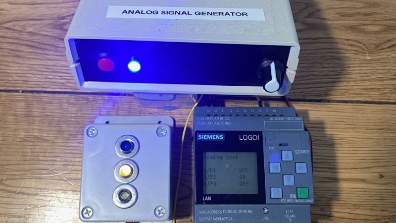
The pressures of such a gig can be enormous, and seem to have weighed on [Tom Goff] enough that he spent a weekend building a junk bin analog signal generator to replace a loop calibrator that he misplaced. Two process control signaling schemes were to be supported — the 0 to 10 VDC analog signal, and the venerable 4-20 mA current loop. All that’s needed for both outputs is an Arduino and an LM358 dual op-amp, plus a few support components. The 0-10 V signal starts as a PWM output from the Arduino, with its 0-5 V average amplified by one of the op-amps set up as a non-inverting amp with a gain of 2. With a little filtering, the voltage output is pretty stable, and swings nicely through the desired range — see the video below for that.
The current loop output is only slightly more complicated. An identical circuit on a separate Arduino output generates the same 10 V max output, but a code change limits the low end of the range to 1 V. This output of the op-amp is fed through a 500-Ω trimmer pot, and the magic of Ohm’s Law results in a 4-20 mA current. The circuit lives on a piece of perf board in a small enclosure and does the job it was built for — nothing fancy needed.
And spoiler alert: [Tom] found the missing loop calibrator — after he built this, of course. Isn’t that always the way?


I see no point in using PWM and a µC here, since the voltage from the pot could go directly to the OpAmp buffers, except that it saves maybe 1€ for another pot, some resistors and drilling a hole. Only if this thing could also provide programmable sequences for automated testing, using an Arduino would be justified.
Exactly. Also, the current loop driver leaves much to be desired – if there is significant additional external resistance (e.g. driving a long length of cable) then you’ll need to adjust the trimpot to account for this. (Ah, I see he mentions this). Better would be to incorporate the trimmer in the feedback loop of the opamp so it produces a genuine constant-current output.
“found the missing …” does mean he buy it back? :b
Although it can be fun to make such devices, there are a lot of off the shelf units that can be purchased for low $ (anywhere fro $10 to $200). A number of these units are handheld and battery/USB powered and so are very easy to bring along and leave in one’s tool pouch. One can certainly spend the big $ on high end devices, but only if you need that level of precision… and if your company pays for them.
If you’re into such things, some commercial offerings I’ve seen online but not used myself:
https://plctools.com/
Nice! Even if it’s not perfect, there’s always room for people to diy more stuff in the industrial controls space.
Am I missing something? I do not understand the current loop regulation principle from the schematic. Is the current sensed somewhere off-circuit and then regulated in a software feedback loop?