It looks like [Michal Zalewski] is raising the next generation the right way. First, his eldest son asks for help building a one-bit computer from discrete transistors. Not to be left behind, his little brother then asked for help with an even more retro project, which resulted in this partially relay-based calculator. Maybe there is some hope for the future.
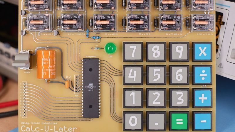
Now, purists will no doubt notice the ATmega64 microcontroller sitting in the middle of the main PCB on this project and cry “Foul!” But perfect is the enemy of done, and as [Michal] explains, at $6 a pop for the Omron relays he and his son chose, there’s only so far you can go with relay logic before you’re taking out a second mortgage. So the relays are limited to the ALU of the calculator, along with the drivers for the six seven-segment LED displays. The microcontroller is just there for housekeeping functions like scanning the keyboard and decoding digits. All the actual calculations are in the relay logic, not silicon. And we’d be remiss not to praise his son’s stylistic choices for this design — that it uses relays with clear covers, and that it has single-sided PCBs with curvy, hand-drawn traces traces that look hand-drawn on old-school yellow substrate. [Michal]’s heart must swell with pride to have fathered someone with such exquisite taste.
For his part, [Mikal] did some really good documentation for this build, including excellent descriptions of Boolean math with half- and full-adders and how relays are used to create the basic logic gates that comprise them. The calculator itself is still a work in progress, with microcontroller code still in development, but it’s working enough that you can enjoy the display driver’s clickiness in the video below. If that doesn’t do it for you, we’ve got other relay calculators to scratch that click itch.


gorgeous. the design and implementation is fantastic. even without knowing anything about it, you can practically see where information is coming from and to where it flows. You don’t even have to know what the device is ahead of time. For example, the keypad is clearly a 4×4 matrix, with the info gently flowing into the obvious microcontroller in the middle, where the gentle traces coming out of it lead off to do some other important work.
This is a study in form-follows-function and belongs in an art museum or an exhibit in a computer science museum.
That board looks just like a hand-taped, liquid-tinned, hand-silked board from 1981. Lovely. Mission accomplished.
I second this. The curvy traces are actually useful, too. At higher frequencies, edges with a hard angle may cause reflection.
So it’s combining beauty and elegance with usefulness in perfect harmony. Kudos.
Building this certainly isn’t counter-productive!
– Oh my, puns! 🙄😂
His design really counts and adds to a total great build ! The great sounds of the relay clicks don’t subtract from but multiply the coolness.
That’s my kind of ASMR. It’d be fun to make a few boards with different families of relays to explore different sound profiles.
In the category of “hope for the future” for halloween I built a bunch of star shaped boxes that sit on the ground and when you step on them they change color. Next year they will form a game. The kids absolutely loved them.
I was impressed with 3 kids who came – one wanted to know which parts were 3D printed, one was trying to figure out the delay of the color shift algorithm and one was trying to figure out how to turn them all red (color selection is random)
So yes, here’s to up and coming nerds.
Here’s the video of multiplication, which didn’t make it into the summary: https://vimeo.com/880389001/c315de4c25
Argh. Let’s try again: https://www.youtube.com/watch?v=giGz6aJgSXw
I participated in a “trunk or treat” last Sunday. I made a simple beanbag toss game using flower pots, IR LEDs, and a Nintendo Switch (running Game Builder Garage). A couple of teens wanted to know how it was coded, and a few perceptive younger kids recognized the Joy Con I was using for its IR camera.
Do you have a part number for the push switches ?
These are JF series switches from NKK. They have them in round and square varieties:
https://www.nkkswitches.com/pdf/JFnonilluminated-1.pdf
Here’s the blue square one:
https://www.digikey.com/en/products/detail/nkk-switches/JF15SP1G/1052217
They are really cool. A bit pricey, but fantastic for “bare PCB” projects like this.
Thanks for catching my mistake and so kindly pointing it out. Fixed it for you.
Die Relais haben die Bestellbezeichnung G6C-1117P-US 5VDC ,
Hat einen 10A/250VAC Schließer Kontakt.
Ist Flussmitteldicht,
Die Spulennennleistung beträgt 200mWatt.
A calculator that subs as a drum kit…