The Other Kind Of Static Hazard To Your Logic Circuits

We’ve all heard of the dangers of static electricity when dealing with electronics, and we all take the proper precautions when working with static-sensitive components — don’t we? But as much as we fear punching an expensive hole in a chip with an errant spark, electrostatic discharge damage isn’t the only kind of static hazard your digital designs can face.

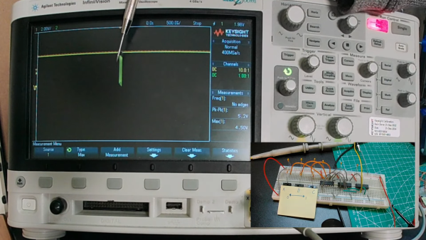
To be fair, the static hazard demonstrated by [Shane Oberloier] in the video below isn’t really an electrostatic problem. “Static” in this case refers to when a change to an input of a logic circuit gives an unexpected output until the circuit stabilizes. The circuit shown is pretty simple, with three inputs going into a combination of AND and NOT gates before going into an OR gate. The static hazard manifests as a glitch in the output when the middle input line’s logical state is toggled; according to the circuit’s truth table, the output shouldn’t change under these conditions, but the oscilloscope clearly captures a high-low-high blip. [Dr. Shane]’s explanation of why this happens makes perfect sense: the inverter on that input line has a brief but non-zero propagation time, putting the whole circuit in an ambiguous state before finally settling down to the correct output value.

So how do you fix something like this? This gets into the Boolean weeds a bit, and we won’t pretend to fully understand it, but at least for this case, [Dr. Shane] was able to add a single AND gate to sum the two other inputs and pipe the output into another input of the OR gate. That has the effect of canceling out the race condition caused by the inverter, but at the expense of a more complicated circuit, of course.

We found this to be a fascinating and informative discussion of a potential pitfall in logic design. But, if you still want to see some MOSFETs executed with static electricity, who are we to object?

Continue reading “The Other Kind Of Static Hazard To Your Logic Circuits”

Partial Relay-Based Calculator Puts The Click Where It Counts

It looks like [Michal Zalewski] is raising the next generation the right way. First, his eldest son asks for help building a one-bit computer from discrete transistors. Not to be left behind, his little brother then asked for help with an even more retro project, which resulted in this partially relay-based calculator. Maybe there is some hope for the future.

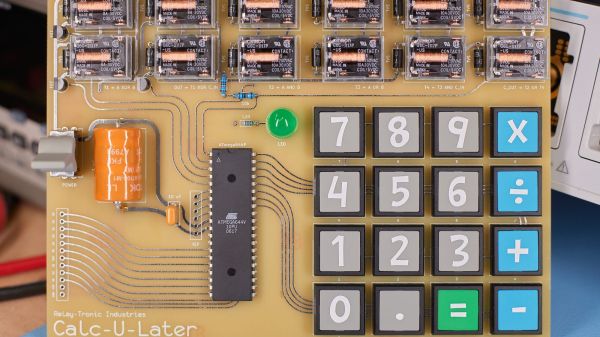
Now, purists will no doubt notice the ATmega64 microcontroller sitting in the middle of the main PCB on this project and cry “Foul!” But perfect is the enemy of done, and as [Michal] explains, at $6 a pop for the Omron relays he and his son chose, there’s only so far you can go with relay logic before you’re taking out a second mortgage. So the relays are limited to the ALU of the calculator, along with the drivers for the six seven-segment LED displays. The microcontroller is just there for housekeeping functions like scanning the keyboard and decoding digits. All the actual calculations are in the relay logic, not silicon. And we’d be remiss not to praise his son’s stylistic choices for this design — that it uses relays with clear covers, and that it has single-sided PCBs with curvy, hand-drawn traces traces that look hand-drawn on old-school yellow substrate. [Michal]’s heart must swell with pride to have fathered someone with such exquisite taste.

For his part, [Mikal] did some really good documentation for this build, including excellent descriptions of Boolean math with half- and full-adders and how relays are used to create the basic logic gates that comprise them. The calculator itself is still a work in progress, with microcontroller code still in development, but it’s working enough that you can enjoy the display driver’s clickiness in the video below. If that doesn’t do it for you, we’ve got other relay calculators to scratch that click itch. Continue reading “Partial Relay-Based Calculator Puts The Click Where It Counts”

Vacuum Tube Logic Hack Chat

Join us on Wednesday, December 9th at noon Pacific for the Vacuum Tube Logic Hack Chat with David Lovett!

For most of us, circuits based on vacuum tubes are remnants of a technological history that is rapidly fading from our collective memory. To be sure, there are still applications for thermionic emission, especially in power electronics and specialized switching applications. But by and large, progress has left vacuum tubes in a cloud of silicon dust, leaving mainly audiophiles and antique radio enthusiasts to figure out the hows and whys of plates and grids and filaments.

But vacuum tubes aren’t just for the analog world. Some folks like making tubes do tricks they haven’t had to do in a long, long time, at least since the birth of the computer age. Vacuum tube digital electronics seems like a contradiction in terms, but David Lovett, aka Usagi Electric on YouTube, has fallen for it in a big way. His channel is dedicated to working through the analog building blocks of digital logic circuits using tubes almost exclusively. He has come up with unique circuits that don’t require the high bias voltages typically needed, making the circuits easy to work with using equipment likely to be found in any solid-state experimenter’s lab.

David will drop by the Hack Chat to share his enthusiasm for vacuum tube logic and his tips for exploring the sometimes strange world of flying electrons. Join us as we discuss how to set up your own vacuum tube experiments, learn what thermionic emission can teach us about solid-state electronics, and maybe even get a glimpse of what lies ahead in his lab.

join-hack-chatOur Hack Chats are live community events in the Hackaday.io Hack Chat group messaging. This week we’ll be sitting down on Wednesday, December 9 at 12:00 PM Pacific time. If time zones have you tied up, we have a handy time zone converter.

Click that speech bubble to the right, and you’ll be taken directly to the Hack Chat group on Hackaday.io. You don’t have to wait until Wednesday; join whenever you want and you can see what the community is talking about.

Continue reading “Vacuum Tube Logic Hack Chat”

Centennial Birthday Of Claude E. Shannon The Math And EE Pioneer

Dr. Claude E. Shannon was born 100 years ago tomorrow. He contributed greatly to the fields of engineering, communications, and computer science but is not a well known figure, even to those in the field. However, his work touches us all many times each day. The network which delivered this article to your computer or smartphone was designed upon important theories developed by Dr. Shannon.

Shannon was born and raised in Michigan. He graduated from the University of Michigan with degrees in Mathematics and Electrical Engineering. He continued his graduate studies at Massachusetts Institute of Technology (MIT) where he obtained his MS and PhD. He worked for Bell Laboratories on fire-control systems and cryptography during World War II and in 1956 he returned to MIT as a professor.

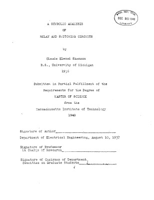
shannon-0Shannon’s first impactful contribution was his masters thesis which took the Boolean Algebra work of George Boole and applied it to switching circuits (then made up of relays). Before his work there was no formal basis for the analysis of switching systems, like telephone networks or elevator control systems. Shannon’s thesis developed the use of symbolic notation to represent networks and applied simplifying rules to optimize the system. These same rules later translated to vacuum tube and transistor logic aiding in the development of today’s computer systems. The thesis — A Symbolic Analysis of Relay and Switching Circuits — was completed in 1937 and subsequently published in 1938 in the Transactions of the American Institute of Electrical Engineers.

Shannon’s doctoral work continued in the same vein of applying mathematics someplace new, this time to genetics. Vannevar Bush, his advisor, commented, “It occurred to me that, just as a special algebra had worked well in his hands on the theory of relays, another special algebra might conceivably handle some of the aspects of Mendelian heredity”. Shannon’s work again is revolutionary, providing a mathematical basis for population genetics. Unfortunately, it was a step further than geneticists of time could take. His work languished, although interest increased over time.

Continue reading “Centennial Birthday Of Claude E. Shannon The Math And EE Pioneer”

From Gates To FPGA’s – Part 1: Basic Logic

It’s time to do a series on logic including things such as programmable logic, state machines, and the lesser known demons such as switching hazards. It is best to start at the beginning — but even experts will enjoy this refresher and might even learn a trick or two. I’ll start with logic symbols, alternate symbols, small Boolean truth tables and some oddball things that we can do with basic logic. The narrative version is found in the video, with a full reference laid out in the rest of this post.

Invert

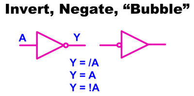
1The most simple piece of logic is inversion; making a high change to low or a low change to high. Shown are a couple of ways to write an inversion including the ubiquitous “bubble” that we can apply almost anywhere to imply an inversion or a “True Low”. If it was a one it is now a zero, where it was a low it is now a high, and where it was true it is now untrue.
AND

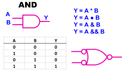
2Moving on to the AND gate we see a simple truth table, also known as a Boolean Table, where it describes the function of “A AND B”. This is also our first opportunity to see the application of an alternate symbol. In this case a “low OR a low yields a low”
NAND

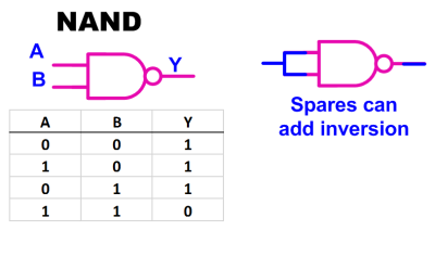
3Most if not all of the standard logic blocks come in an inverted form also such as the NAND gate shown here. The ability to invert logic functions is so useful in real life that I probably used at least three times the number of NAND gates as regular AND gates when doing medium or larger system design. The useful inversion can occur as spares or in line with the logic.

Continue reading “From Gates To FPGA’s – Part 1: Basic Logic”

7400 Series Logic Simulator

logic

Atanua is a real time logic simulator to help people learn some of the basics of electronics. Focusing mainly on logic, as opposed to power, this is a fantastic tool to learn with. They have done a fantastic job of making it easy to use as well as good looking. We can see this as being a must have piece of software for any hacker. There is a free version available as long as you aren’t using it commercially.

[Thanks ellisgl]