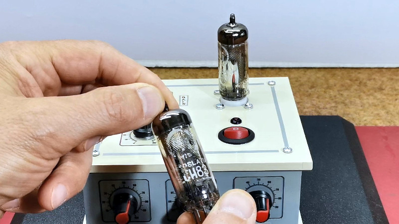
When most people think of tube circuits, the first thing that comes to mind is often the use of high-voltage power supplies. It wasn’t a given for tube circuits, though, as a range of low-voltage devices were developed for applications such as car radios. It’s one of these, an ECH83 triode-heptode, which [mircemk] has taken as the basis of an audio preamplifier circuit.
The preamp circuit is pretty simple, being a two-stage single-ended design using both halves of the tube. Between the two is a three-band tone control circuit as used in classic guitar amplifiers, making for a serviceable and easily achievable way to chase that elusive “valve sound.”
There is much discussion among audio enthusiasts about the supposed benefits of vacuum technology as opposed to transistors in an amplifier. Much of it centres around the idea that tubes distort in the even harmonics while semiconductors are supposed to do so in the odd harmonics. Still, we’d be inclined to spot a bit of snake oil instead and point to early transistor amplifiers simply being not very good compared to the tube amps of the day. That said, a well-made tube amplifier set-up will sound just as amazing as it always did, and since this one is paired with a matching power amp we wouldn’t say no to it ourselves.
If you fancy messing about with tubes for not a lot, there’s a cheap module for that.


I don’t recall 0V control grid bias being a thing (for linear modes, anyway). I’ll have to review previous topologies. The microphonic enhancing mechanical design is in keeping with guitar culture, although it doesn’t look to be ‘tossable’ (for roadie survival).
It isn’t 0V. The grid bias is provided by the grid current and it’s associated voltage drop across the grid resistor. That was the usual way EF86 microphone input stages in consumer gear were built, but with a grid resistor in the range of 2..10 MΩ. It allowed the cathode to be grounded, trading hum from the AC heater for noise and distortion – and it saved a couple of parts. Back then 50dB SNR and 2% THD qualified as hi-fi, today it would be called crappy. Audiophools still like it.
“When most people think of tube circuits, the first thing that comes to mind is often the use of high-voltage power supplies.”
Miniature tubes/battery tubes like the EF98 were also used in car radios.
12v was fine as an anode voltage to get it going *properly* (EF95 needed higher voltage ca. 90v; a hack was to modify a grid voltage, putting the grid “high”) .
That’s why it was used later on in the German Radiomann construction kit, too, I suppose (original was DM300 or something. I’d to ask my grand grand father.)
http://www.r-type.org/exhib/aaa0481.htm
The EF97 could be used as a substitute, too, in many cases.
Here, grid 1 and 3 were internally shorted, I *think*.
Anyway, speaking under correction.
The good thing about tubes is that they softly into saturation, too.
They’re still nice as an RF frontend, because they can handle higher power signals coming from long wire antennas.
EF97 and EF98 share the same mechanical construction and pinout, they only differ in how the control grid is wound, giving the EF97 remote-cutoff and the EF98 sharp-cutoff characteristics.
“being a two-stage single-ended design using both halves of the tube”
being a two-stage single-ended design using both halves of the valve
FTFY
B^)
Valve, tube – which one is correct depends on what side of the pond you are from.
I was just playing with the similar spelling of halve and valve.
(And was a bit surprised by [Jenny] using the word “tube”)
Probably meant “lube”?
I have a Digitech 2112 SGS with two 12ax7 for tube distortion and it has analog ( transistor) distortion.
One can run them on either side of the stereo spectrum, have a mix of both or one or the other .
There is something about tubes that IR or AI can’t achieve, tube offer more sensitive tonal shift and you can “feel” it when you play with the guitars volume knob .
Serviceable? Are any of these starved voltage tubes still around? My first radio was a 6V car radio. I could run it on my Lionel power supply. The vibrator quit and I had it apart forcing it closed the radio came to life. Those 6 volt DC units could run on AC and had normal home set tubes. My 2nd radio 12V had no vibrator and I wondered how it worked without B+ and weird number tubes. It worked OK not as good as the big stuff. Within a few years tubes left the car.
There are still plenty of tubes for low voltages available, if you know where to look. The ECH83 is identical to the ECH81, used in nearly all European tabletop tube radios as MW/LW mixer after 1952. Those two tubes share the same internal construction (at least if they came out of the Philips imperium), they were just sold with different guaranteed parameter ranges.
The even harmonics for tubes / odd harmonic for solid state is entirely a myth. It simply is not true. Even order harmonics are caused by asymmetrical nonlinearity while odd harmonics are generated by symmetrical nonlinearity. If you examine any active device i.e., tube, transistor, both are generated. This myth may have arisen due to circuit topology – push pull stages tend to cancel even harmonics as they are out of phase on each side of the push-pull pair – almost all solid state amps are push pull topologies, where many tube amps are single ended. There are plenty of push pull tube amps, and it’s possible although not common to make a single ended solid state amp
I guess this myth originated with early PP transistor amps before useful silicon PNP power transistors were available. Those constructions often used a germanium PNP or a Sziklai pair instead of the not yet existing silicon PNP, resulting in an asymmetrical output stage, much more asymmetrical than a tube PP amp with the usual tube tolerances.
“is entirely a myth”
Along with all the other myths about tube vs solid state.
I will take a high quality solid state amp over tube any day.
Not entirely, I think. Tubes go into softly saturation if overloaded, while transistors just got deaf.
I saw this myself when I built two direct-conversion receiver for receiving DRM radio via sound card.
One was based on an BC548, the second based on an EF95.
The BC548 couldn’t handle the long wire antenna, while the EF95 had modest amplification but didn’t go deaf.
Personally, I think that we shouldn’t forget were the field-effect transistors do come from.
They’re basically tube technology on semiconductor basis, minus the toughness.
“Tubes go into softly saturation if overloaded…”
That’s because the tubes themselves have a rather low open-loop gain compared to transistors and tube amps didn’t use much negative feedback due to the nasty side effects of inductive components and parasitic capacitances. If you build a tube amp with sufficient gain and tight feedback (op-amp style), it will clip hard, just like semiconductors do.
Your’s was an interesting comment in the tube v. transistor debate. I don’t think that I’ve heard such before.
“If you build a tube amp with sufficient gain and tight feedback (op-amp style), it will clip hard, just like semiconductors do.”
Yes, I assume that’s possible, I suppose. Many tube simulator circuits had been created over tge years.
My point mainly was about tubes being very forgiving.
They can handle mismatches much better than transistors.
if you short a tube, it won’t die instantly like a transistor does.
That’s one of the reasons linear amplifiers using tubes kept being relevant long after transistors were introduced.
If a tube is dropped, it shatters. Glass is not forgiving.
Either way, I find it a bit strange that I have not seen any “definite” product to answer the question about tube vs transistor.
Aka; any reasonably good amplifier should suffice (this is ofc solid state), and add in some presets for the “sound” you want. Inputs and outputs should include some headroom to be able to emulate the softer rolloff of tubes etc.
Needs a really good GUI for interface as well ofc, suited to the target audience.
Presets could be:
* Tube
* Transistor (early)
* Transistor (later)
* Model t-tube radio
* 50s sound, 60s sound, etc
* Etc
Could also be crowd sourced so you could set up and share your favorite teenage radio sound. Possibly it could also have some support for input/output characteristics; custom impedance curves for what should happen if you “overload” the input, for example. To induce any desired distortion you would get from the source.
Sounds like something that could be incorporated into cell phone and iPod software too.
[edit] develop an algorithm to add a nasal twang and a steel guitar to make any song “Country”.
B^)
“Either way, I find it a bit strange that I have not seen any “definite” product to answer the question about tube vs transistor.”
Me, too. I wished there was more information available.
I also often wonder what could have the Nuvistor been evolving into if it’s development wasn’t canceled in favor of cheaper transistors.
The high maximum frequency, low operating voltage and low self-noise of Nuvistors used to be excellent qualities.
That’s why it was used in oscilloscopes, satellites and high quality microphone amps.
Scopes as late as from the 80s/90s had used them somewhere inside of their circuits.
Not bad for a technology that essentially hadn’t been improved since the 1960s.
But are you a discerning electric guitar player or does the high frequency harmonic cloud mean nothing to you??
ECH83 I used once to make a low voltage regenerative receiver. Re tube sound, clipping is soft, not hard as it is with transistors. Also, “tube sound” might partly be “transformer sound”, since most tube amps use output transformer. That thing definitely changes the sound.
Thanks, I hadn’t heard of that argument before.
I visited a museum on guernsy it had a display of german witld wzr 2 radio and equipment and parts my wife and other women visitors seemed to br amused by the box of vibrators they had no no idea of them being radio parts and thought they had another purpose
Whatever it takes to keep the troops happy.
B^)
:) I recently had to explain a multivibrator to a female ;) She never heard of it before and was quite amused initially.