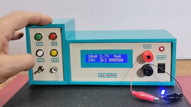
[mircemk] built a slick-looking LED tester with a couple handy functions built in. Not only can one select a target current to put through an LED, but by providing a target voltage, the system will automatically calculate the necessary series resistor. If for example the LED is destined for 14 V, this device will not only show how the LED looks at the chosen current, but will calculate the required resistor to get the same results on a 14 V system.
The buttons on the left control the target current and the voltage of the destination system. Once an LED is connected it will light up and the display indicates the LED’s forward voltage, the LED current, and the calculated series resistor value to obtain the same result at the selected target voltage. It’s a handy way to empirically dial in LED brightness values without needing to actually set up any particular test environment.
On the inside there’s little more than a handful of passive components, an Arduino, an LCD display, and a few buttons. This kind of tool reminds us of the highly clever component testers that hit the hobbyist scene years ago, showing what kind of advanced tricks a modern microcontroller is capable of with the right programming. (Here’s a look at how those work, if you’re interested in some deeper details.)
[mircemk] demonstrates his tool in the video, embedded below. We particularly like the attention he paid to the enclosure, giving it a very functional layout. It goes to show that when designing something, it’s never too early to consider enclosure and UI layout.


Connecting alligator clips seems time-consuming and clumsy. Perhaps a two-prong socket to simply stick the LED in, like the old transistor testers of yesteryear. Or two V-slotted plates to jam the leads in quickly?
I understand why they’ve gone this route, but having a two-prong socket *in addition to* the alligator clips would still be a massive advantage.
And the reason is: Some LEDs come as COBs, or chip-on-board, where a whole bunch are laid directly onto a substrate, so there’s no legs to plug into anything.
1 to 99V how? Looking at the graphical schematic he can’t even vary the voltage to that LED? Just gives it different PWM values from a 5V pin (software bit banging of pin A3 it seems), and it doesn’t even look like they are truly low pass filtered before going to the LED. There’s no circuit element in here to generate high voltages (not that such voltages would be healthy for most component anyway), or to vary low voltages. Pin A2 seems to be able to read a low pass filtered voltage, but there is no means to supply this voltage to the LED. I’d be intrested to see a deeper analysis of what is going on, because I’m not sure that generating a PWM wave really lets you assess how an LED will behave at different true voltages and with different resistances in series with it. Might want to look in to an SPI controlled potentiometer (higher voltage rated) wired from Vcc to Gnd, then pass the output of that (high source resistance) to an (again higher voltage rated, as I guess he wants to be able to give >5V for some circumstances) op amp or a transistor acting as a voltage follower.
It’s math. All the circuit does is find out the forward voltage and compute the resistor value based on target voltage and current. The whole circuit runs on fixed 5v.
Example: circuit determines the LED has a forward voltage of 1.8v and you have 99v, 10mA set, it will do this: 99v-1.8v/0.01A and come up with 9720 ohms resistor. (10k would be the nearest common value)
I’d recommend adding a PWM knob. When I use an LED, I have to decide how much current to put through it, and what duty cycle to use, and I want to see how bright it will be with those choices.
This is doing exactly the same thing when it varies the current.
Interesting project !
Bonus for the banana plugs – for scale…
Test LEDs in the dark, otherwise part of the measured behaviour is them generating voltage from light hitting them, because after all you can use them to sense light as well as create it.
When driving LEDs, please please dont max out the current (usually 20mA, or 100% PWM) just “because”. Please consider the user and the environment in which it will be used.
I have all sorts of devices in dark rooms (reading lamps, USB hubs, etc) that have LEDs blasting at full brightness when just a minor glow would suffice. So annoying to need tinting stickers over them, when a little more thought would have used a larger resistor, saved some power, and not been so blinding.
Thought about selling these I just don’t have time to build one
That music on all his videos is so repetitive and annoying that I can’t watch his videos.
It’s a pity since it’a pretty decent channel in my view, it’s just that music he uses, over and over and over.
This is a nice project. I would add a zif socket to make testing eaiser. And also maybe a small PCB with SMD pads.
My problem is that I never know what the current rating of the LED is. I have bunch of LEDs I got from Ali and forget to make a note of the current. I can measure the forward voltage with a component tester, but it is 20mA, or 15mA, or 10mA. What is the best way of finding that out? Use typical current ratings?