If you’re designing a universal port, you will be expected to provide power. This was a lesson learned in the times of LPT and COM ports, where factory-made peripherals and DIY boards alike had to pull peculiar tricks to get a few milliamps, often tapping data lines. Do it wrong, and a port will burn up – in the best case, it’ll be your port, in worst case, ports of a number of your customers.
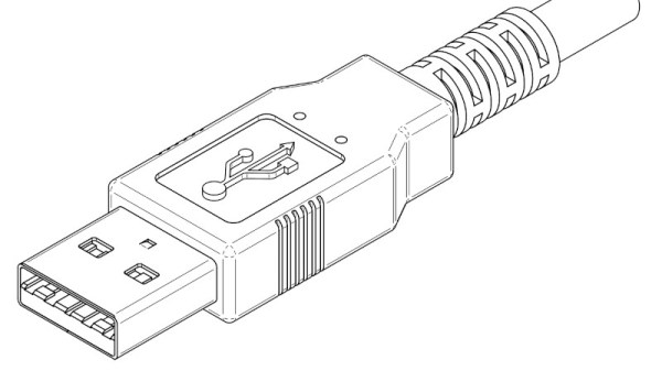
Having a dedicated power rail on your connector simply solves this problem. We might’ve never gotten DB-11 and DB-27, but we did eventually get USB, with one of its four pins dedicated to a 5 V power rail. I vividly remember seeing my first USB port, on the side of a Thinkpad 390E that my dad bought in 2000s – I was eight years old at the time. It was merely USB 1.0, and yet, while I never got to properly make use of that port, it definitely marked the beginning of my USB adventures.
About six years later, I was sitting at my desk, trying to build a USB docking station for my EEE PC, as I was hoping, with tons of peripherals inside. Shorting out the USB port due to faulty connections or too many devices connected at once was a regular occurrence; thankfully, the laptop persevered as much as I did. Trying to do some research, one thing I kept stumbling upon was the 500 mA limit. That didn’t really help, since none of the devices I used even attempted to indicate their power consumption on the package – you would get a USB hub saying “100 mA” or a mouse saying “500 mA” with nary an elaboration.
Fifteen more years have passed, and I am here, having gone through hundreds of laptop schematics, investigated and learned from design decisions, harvested laptops for both parts and even ICs on their motherboards, designed and built laptop mods, nowadays I’m even designing my own laptop motherboards! If you ever read about the 500 mA limit and thought of it as a constraint for your project, worry not – it’s not as cut and dried as the specification might have you believe.
Continue reading “USB And The Myth Of 500 Milliamps”


 On paper, a light bulb lights up when you put current through it. In real life, it is a bit more complicated. An incandescent filament starts off as almost a dead short and draws a lot of current for a very brief time. As the current flows, the filament gets hot and the resistance goes up. That reduces the current draw. This effect — known as inrush current — is the scourge of designers trying to turn on light bulbs with transistors or other electronic switches.