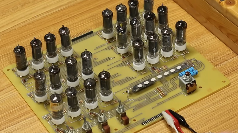
We have occasionally featured vacuum tube computers here at Hackaday and we’ve brought you many single board computers, but until now it’s probable we haven’t brought you a machine that combined both of these things. Now thanks to [Usagi Electric] we can see just such a board, in the form of his UE-0.1, a roughly 260 by 210 mm PCB with 24 6AU6 pentodes on board that implements a simple one-bit CPU.
The architecture starts with the MC14500B 1-bit microcontroller, which was the subject of a previous vacuum tube computer. People found the unusual architecture difficult to understand, so this board is an even simpler take. It doesn’t have all the features of the Motorola original but it is (just) enough to be a CPU.
The tubes are arranged in groups of four with heaters in series from a 24 V supply, while the inputs and clock come in the form of on-board suitably retro-looking switches. The final touch is a VFD of the type used in bar graphs, were used to show the state of the various bits. It’s a fully working computer in the simplest sense, and definitely worth a look in the video below the break.
It would be interesting to see whether the tube count could be reduced further, or is this a record. The number of physical devices could be cut by using tubes with more than one device in them such as double-triodes, but perhaps that would be cheating.
Meanwhile, if you think vacuum computing is all about the old stuff, perhaps you should look at the state of the art.


WOW, if I were still in college with the memory I had and the spare time to go along with it
YES, and NO. And then MAYBE.
As a guy who spent six years in the Air Force working on vacuum tube equipment from the 1950s and 60s, I would be happiest if I never saw another triode or pentode. So NO. Exceptions made for CRTs, of course.
BUT, I can see implementing this in either bipolar DTL-like logic using 2N3904 transistors, or possibly NMOS using 2N7000-ish MOSFETs. So YES.
MAYBE I need to look into the MC14500B again, this time with the purpose of seeing how memory gets connected to it. I mean, I see A2..A0 signals, so presumably that’s to access 8 bits of memory, which .. not very useful! I mean, as I recall, the application information in the datasheet shows an external counter that feeds program addresses to a ROM, so that any amount of program storage is possible, but I think it was pretty limited on jumps. Sigh. Now I have to go look.
Oh! It’s actually more interesting than that: the application circuit (http://www.bitsavers.org/components/motorola/14500/MC14500B_Industrial_Control_Unit_Handbook_1977.pdf, page 1) gets a lot more useful stuff directly from the ROM, allowing it to send binary fields to input and output multiplexers. This means that memory is also not inherently limited, since you can use as many multiplexers as you can feed with bits from the program ROM, and if you use memory-mapped I/O, you can similarly fan-in and fan-out any number of I/O signals. It doesn’t look like [Usagi Electric] has implemented any of this extra (but necessary for a working computer) hardware, being content for the moment to just toggle instructions in and look at the states of the internal signals. But anyway, hey, I could drive an Intel 2102 (1k x 1 static RAM) with something like that! Which, duh, is why computers have address fields in their instructions. (Which helps for direct memory addressing, but needs more help for things like indexed or indirect addressing.) Note that that particular application circuit didn’t show any possibility of implementing a Jump instruction, but by using a program counter that has a “load” input to preset it to a given number, this could also be fed back from the address field to implement jump instructions. I don’t know why I missed this before – this makes the size of the ROM (both word length and number of words) the principal determinant of machine capability. Huh.
You know, now that I think about it, the PDP-8/S was a 1-bit computer that had firmware to make it function as a 12-bit machine, making it software-compatible with the rest of the PDP-8 line, and I think it probably used fundamentally the same architecture as an MC14500B system.
Now, if I wanted to make a bipolar or NMOS version of this, it wouldn’t be too much of a stretch to use semiconductor ROM and RAM with it, since the MC14500B came out in 1976, when PROMs and SRAMs were in common use. [Usagi Electric] would have to come up with older, more contemporaneous memory technologies to avoid acute cognitive shock in his system. But then, he probably has a lot of that already in his shop! (Older memory technologies, that is, not acute cognitive shock.)
The 8/S uses no such firmware. It is a purpose-built, bit-serial architecture.
Oh, you gotta use 1000V B+, and some really big IGBT’s. The output current could be up to 400 Amps. You could directly drive 120V light bulbs for indicators. Yeah, baby let’s start some fires. You could implement the fabled Intel “Halt and catch fire” instruction.
Hey, How about an AC B+ that runs on 60Hz. The power could also be the clock. 60 instructions per second (50 instructions in Europe).
No old man, please don’t do that.
Power nets aren always reliable.
Using it for clocks is lame, I think.
We “just” had this issue when the speed was too slow, then too fast (for correction).
https://www.theguardian.com/world/2018/mar/08/european-clocks-lose-six-minutes-dispute-power-electricity-grid
Had caused a lot of radio alarm clocks to be running at wrong time.
The silliest thing was the correction idea, days later. Because, users had corrected their alarm clocks just before on their own.
So they ran at wrong time TWICE. Sigh.
If you need accurate clock, please use something like a time signal station or GPS. 🙂👍
DCF-77 time format, for example, uses accurate pulses that can be used without electronics, even.
The radio receiver can drive an electro-mechanical clock.
Nice! How are you getting the tubes to run on 24V? I didn’t think tubes would work at such a low voltage. A long time ago, I use to work on a very old analog computer made with tubes. It was 120 separate op amps that had a +-100V swing. Yeah, if you got on that “One” it was very painful. It was quite cantankerous, and woke up in a different mood every day. It had a personality all it’s own. It took about 10 minutes to fully wake up. But when it was up and running it did it’s job quite well. When can we expect Microsoft to recompile Windows 11 to run on this CPU?
When I was a kid, I got a hand-me-down Knight-Kit 100-in-one electronics kit. It included three transistors and a 12AU7 dual triode. All of the projects ran on about 24V. Circuits that needed high-impedance active devices used the tubes, those that didn’t used the transistors. Many projects used both. In particular, AM radio projects using the tube for RF gain and transistors for audio worked much better than the all-transistor ones. The down side of using tubes at low voltage is that the plate resistors need to be scaled down, and this results in lower gain. Most tubes themselves work fine at lower voltages. For digital projects, higher voltage translates to higher power requirements, a fundamental fact that holds true today for computers.
I think the same. In addition, reducing the heater voltage from 6,3v to 6v (lantern battery), 5v (TTL voltage) or 4,5v (3R12 battery, previously popular in Europe) doesn’t reduce functionality much, but noticeably increases lifetime of a tube. 🙂