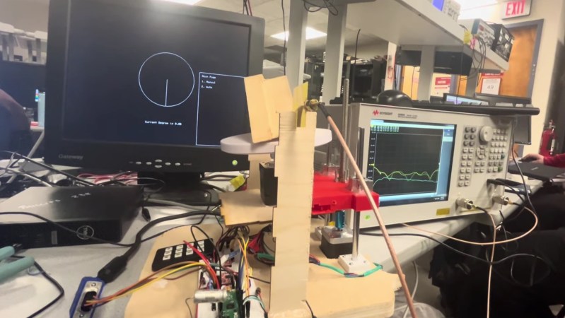
Microwave imaging is similar to CT imaging, but instead of X-rays, the microwaves are used to probe the structure and composition of an object. To facilitate experimentation with microwave imaging, [Zehao Li] and [Kapil Gangwar] developed a system based on the RP2040 to control the height and rotation of a test object.
Their control system has a refreshingly physical user interface—a keypad. The keypad is used to configure the object’s position and the scanning step size, while user menus and the sample position are displayed in a clean and uncluttered interface over VGA. The RP2040 runs a multi-threaded program to handle user input, VGA display, and precise driving of two stepper motors for sample positioning.
The microwave imaging was performed by measuring the RF transmission over 2.5-8 GHz between two Vivaldi antennas on either side of the sample at a variety of angles. 2D cross-sections of the test object were reconstructed in Matlab using filtered back-projection. In this proof-of-concept demonstration, a commercial vector network analyzer was used to collect the data, but one could imagine migrating to a software defined radio (SDR) in the future.
A video demonstrating the system is embedded below the break. If you’re interested in DIY radio imaging, you might be interested in this guide to building your own synthetic aperture radar setup, or this analysis of an automotive radar chip.


The audo of the video starts out at normal volume, but quickly finds a closet to go hide in. I am not interested in doing audio editing for them. It is something they should have done before releasing the video.
The actual audio is still better than some CNN voice garbage imo.
What’s really weird though is their reconstruction (see github.io link). The test object is reconstructed as… a single pixel (the rest is bilinear interpolation) ?!
The wavelength at 8 GHz is 3.7 cm, about 1.5 inches.
I don’t think they can resolve pixels much smaller than the wavelength with a single transmitting antenna.
It’s an interesting bit of research, though.
Who cares? if you want carefully balanced media, turn on your TV.
I´d prefer to have a thorough write-up with schematics and photos anyway…
Hackaday comments are truly the most toxic garbage. It’s a teacher following up with a group of student on their projects, not a how to guide for angry old interweb nerds.
Well said. This group of people is so self-centered, they expect every cross-posted video to be tailored to their preferences.
Regardless of the purpose of they are going to present it for others to see then they should make sure things like the audio are working fine.
Sadly, most of the time when there is a video with an person speaking English with Hindu accent, they receive sarcastic bad comments. Moving on , wondering if the steps of the motor put a limit on the measures/precision/obtained data.
“Microwave imaging is similar to CT imaging, but instead of X-rays,”
More correctly, CT refers to computed tomography, the computations used to create the 3d image, not the specific waves that are used.
https://en.m.wikipedia.org/wiki/Tomographic_reconstruction
“Microwave imaging is similar to CT imaging, but instead of X-rays,”
No, microwave imaging is almost, but not quite, entirely unlike x-ray computed tomography.
It’s much more like ultrasound imaging.
(most ) X-ray Computed Tomography measures the transmission of X rays through the object, assumes straight lines, ignores scattered radiation, is oblivious to refractive index or dielectric constant changes, and can’t measure phase.
Ultrasound and microwave imaging are both almost completely the opposite of that: They usually ignore the transmitted radiation, and the measurements *are scattered radiation. They are exquisitely sensitive to refractive index (~= dielectric constant), the ray paths can appear to bend through the object, and they usually measure signal phase.
(* there exist x-ray computed tomography devices that measure phase, and those that measure scatter, but these are relatively exotic laboratory devices, not seen in normal in medical “CT” imaging)