When it was first introduced in 1968, Fairchild’s 741 op-amp made quite a splash. And with good reason; it packed a bunch of components into a compact package, and the applications for it were nearly limitless. The chip became hugely popular, to the point where “741” is almost synonymous with “op-amp” in the minds of many.
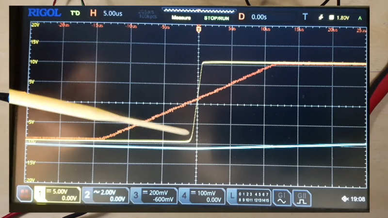
But should it be? Perhaps not, as [More Than Electronics] reveals with this head-to-head speed test that compares the 741 with its FET-input cousin, the TL081. The test setup is pretty simple, just a quick breadboard oscillator with component values selected to create a square wave at approximately 1-kHz, with oscilloscope probes on the output and across the 47-nF timing capacitor. The 741 was first up, and it was quickly apparent that the op-amp’s slew rate, or the rate of change of the output, wasn’t too great. Additionally, the peaks on the trace across the capacitor were noticeably blunted, indicating slow switching on the 741’s output stage. The TL081 fared quite a bit better in the same circuit, with slew rates of about 13 V/μS, or about 17 times better than the 741, and nice sharp transitions on the discharge trace.
As [How To Electronics] points out, comparing the 741 to the TL081 is almost apples to oranges. The 741 is a bipolar device, and comparing it to a device with JFET inputs is a little unfair. Still, it’s a good reminder that not all op-amps are created equal, and that just becuase two jelly bean parts are pin compatible doesn’t make them interchangeable. And extra caution is in order in a world where fake op-amps are thing, too.


The video is exactly 7:41 long. :-)
Back in 1970 we were using the uA709. To add stability mainly in DC applications, a small capacitor was needed in the retro circuit between the minus input and the output.
The uA741 was a uA709 with an added capacitor; if you looked at the die – back then it was pretty easy to open, as it was in a metal TO5-like package – the capacitor was 90% of the die. So, slow slew-rate was built-in!
uA741 has so many other defects compared to actual op-amps…
In the 1990s I worked as a maintenance technician in the final test area of a semi-conductor manufacturer. The ATE we used was of a new design and used a 741 to drive input pins of the device under test. We had way too many failures of the DUTs but when tested with equipment of another manufacturer the same DUTs passed. We identified the 741s slew rate as the problem. I was tasked with replacing ALL the 741s with TL081s on ALL of those machines in our stable (about 64 per machine). We also had to match the slews of each TL081 to be installed, which varied wildly. The test setup to do this was nearly identical to what is shown in this video.
Wait, which 741 brand was this?
741 isn’t 741, there surely were many unlicensed clones.
As it’s with other generic parts (555 timer, 386 amp).
It’s like with saying RG-58 cable is poor, despite the fact that there’s no RG-58 cable as such. It’s a specification, rather. There are countless manufacturers with cables widely differing in quality.
Same goes for 741, 555 and 386. Or those 78xx series linear regulators.
Not all ICs with that description are made of same quality.
It depends on the manufacturer and the manufacturing process (TTL, NMIS, CMOS etc).
That’s what I mean. 741, 555 and 386 are generic terms now.
If we’re more specific, we would say something like LM741, NE555 or LM386.
To me, it’s no surprise that the TL081 worked better.
Because if it’s not a counterfeit, it’s made by a specific company (Texas Instruments or STMicroelectronics?).
A “741” as such is more of a no-name part. That’s what I mean.
Personally, I’ve had gotten a kit for a Pixie TRX once that didn’t work.
What was the culprit? The 386 amplifier.
But not the 386 as such, but the supplied one. It was a Chinese clone that didn’t work.
I’ve replaced it with a LM386 bought in the 1970s and the unit came to life.
Moral of the story: Things are not always the way they seem. 😉
Assuming the 741 tested really was a generic clone, I honestly wouldn’t expect much better from a genuine uA741 or LM741. The specs are pretty unimpressive. It only really is still being made because of its commonality as a well known and good enough “jelly bean” component.
I suppose the fact that it is so slow means it is much less susceptible to RF noise and oscillation. That could prove to be helpful in rough or dirty environments.
As I recall they were TI made 741s. I saw the rails being loaded into the board stuffer machine at the factory.
Thanks to the author for explaining terms as hesheit goes along, so rare in this venue; now I know what “slew rate” means! I’m being sincere. Picture looks like space aliens kidnapped the opamp.
And then there’s the AD8011 and similar, with a slew rate 300 times faster than the TL081 (3500V/us).
Good luck trying to use /any/ current feedback lamp on a solderless breadboard!
I like the rail-to-rail capability of 741 and cousins.
The popular Hamcom modem of the 90s uses an 741 as a comparator.
The modem works as a data slicer, so to say.
Many programs like HamCom, JV-Fax or GSHPC do support it.
But please note that it needs both positive and negative voltage, which it borrows from some RS-232 pins.
Using two 9v batteries for power may work as a workaround for modern serial ports (say, modern PC with a DOS emulation w/ serial pass-through). That gives +9v and -9v.
Some links (not mine).
Circuit:
https://www.discriminator.nl/2-level/
Video:
https://m.youtube.com/watch?v=6rYcxBbmWnM
Rail to rail? The 741 typically has a dropout voltage of at least a volt on both rails
That’s okay for this application, I think.
Thanks for the information, though.
The 741 surely isn’t best in a specific field, but it’s a nice allrounder.
And it’s being forgiving, like so many other historical circuits.
It’s from a time when hams and eletronic hobbyists were still improvising and exploiting flaws in a circuit to their advantage.
Many “trick circuits” (Germ. Trickschaltungen) may depend on these flaws or out-of-spec behaviors.
Using a 741 as a comparator is also a pretty bad idea. Even a TL081 is pretty poor compared to a 339.
Using any opamp as a comparator is a pretty bad idea. The only time it’s (potentially) useful is when you need to check a DC level and have an extra opamp available in a dual or quad opamp.
But things is, it works. 😁
The results are actually not bad.
Have a look a the video.
That comparator modem was an easy to build little helper.
Anyway, I think that’s a matter of attitude, also.
There are people who are practical minded and improvise as best as possible,
and then there are people who can do about everything perfectly on paper.
Op amps can actually do funny things when used as comparators.
A while back, I was teaching an electronics course at a hacker space, and happened to be using lm1458 op amps to teach op amp basics. To demonstrate the concept of “infinite gain”, the lab showed how to use an IP amp as.a.l.comparator .. basically “infinitesimal difference in inputs causes massive difference in output.
I think I used lm1458s because they were popular in some guitar stomp boxes, and a lot of the students were interested in making guitar effects.
In any case, with the LM1458, this comparator-like behavior flips when you try it with voltages near the ps rails. IIRC, if you apply a voltage to the – input that is close to the negative supply rail, the output goes low when the + input is greater than the – input, and goes high when the + input is lower than the – input. Or maybe this occured at the positive extreme .. or maybe both .. I just remember that the behavior was the reverse of the idealized “op amp as comparator”, and that it involved having the voltages being compared being close to one of the rails.
What I do remember with perfect clarity was that I was extremely surprised to stumble across this .. and in front of a class, of all places. In fact, I so surprised that I to took the time to find an LM1458 schematic online, and build an approximate model of it using the Falstad circuit emulator. And the coolest part was that the appropriate model was able to reproduce the behavior.
I dug up email from 14 years ago that describes the situation.more accurately, and that includes the Falstad simulation file.
Take note kiddies .. this is why you should grow up to be oarders.
*************
Very cool — I was able to find the schematic of a 4558 on the web and I reconstructed it in the circuit simulator (www.falstad.com/circuit).
The component values on the amp were just made up, because they were missing from the published schematic, but apparently the circuit is close enough to impersonate the weirdness that we saw when the “+” input gets too low.
Edit the voltage at the “+” input to 5.1 volts, the comparator goes high (as it should) — edit the voltage at the “+” input to 4.9 volts, the comparator goes low (as it should). Edit the voltage to 0.5 volts, the comparator unexpectedly goes high (as it does in real-life)! Definitely not ideal behavior, but very interesting … the root cause of this seems to be that the circuit starts dumping enough current back through the “+” output that it makes things go awry.
$ 1 5.0E-6 10.20027730826997 50 5.0 50
r 192 48 192 112 0 500.0
t 224 128 192 128 0 -1 1.9566294930421035 -0.5063807375045943 100.0
t 256 224 224 224 0 -1 5.0730456829789325 -0.4056782310760392 100.0
w 192 192 224 192 0
w 224 192 224 208 0
w 192 192 160 192 0
w 160 192 160 208 0
t 128 224 160 224 0 -1 4.472753560089531 -0.5056782310760388 100.0
w 256 224 256 256 0
w 256 256 96 256 0
w 128 224 96 224 0
x 102 218 128 224 0 24 “-”
x 98 284 130 290 0 24 “+”
w 224 240 224 320 0
w 224 320 240 320 0
d 240 288 288 288 1 0.805904783
w 240 288 240 320 0
c 240 320 288 320 0 1.0E-11 -8.062692421176575
w 288 288 288 320 0
t 192 400 224 400 0 1 0.500292122889401 0.5010969982358321 100.0
t 192 400 160 400 0 1 0.0 0.49200673033646214 100.0
w 160 240 160 320 0
w 160 320 192 320 0
w 160 416 160 432 0
w 224 416 224 432 0
w 160 432 192 432 0
r 160 432 160 496 0 1000.0
c 192 432 192 496 0 1.0E-11 0.03523970957400622
r 224 432 224 496 0 1000.0
w 192 320 192 400 0
w 160 320 160 384 0
w 224 320 224 352 0
w 224 352 224 384 0
w 224 352 288 352 0
t 288 352 320 352 0 1 -7.973045682978933 0.026954315551415895 100.0
w 288 320 352 320 0
r 352 320 352 224 0 39000.0
t 400 224 432 224 0 1 0.0898954269420269 -6.91183714707222E-8 100.0
t 384 192 352 192 0 1 0.0 -0.0898954269420269 100.0
w 400 224 352 224 0
w 384 192 432 192 0
t 400 128 432 128 0 -1 -0.5374435180191011 -0.5376922758818576 100.0
w 192 144 192 192 0
w 224 128 400 128 0
w 432 144 432 160 0
w 432 192 432 208 0
w 352 208 352 224 0
w 352 176 352 160 0
w 352 160 432 160 0
w 432 160 432 192 0
w 320 336 320 48 0
w 432 112 432 48 0
t 464 160 496 160 0 1 -2.4875786275657674E-4 0.010054676167154497 100.0
w 496 144 496 48 0
w 432 160 464 160 0
r 496 176 496 224 0 25.0
r 496 224 560 224 0 75.0
r 496 224 496 304 0 50.0
w 352 320 432 320 0
w 432 320 464 320 0
w 432 240 432 320 0
t 400 400 432 400 0 1 -8.08964673672799 1.4696514946850592E-9 100.0
w 432 320 432 384 0
w 320 368 320 400 0
w 320 400 400 400 0
t 544 128 576 128 0 -1 0.0 -0.5376922758818576 100.0
w 400 128 544 128 0
w 576 112 576 48 0
w 544 128 544 160 0
w 544 160 576 160 0
w 576 144 576 160 0
r 320 400 320 496 0 5000.0
w 432 416 432 496 0
t 464 320 496 320 0 -1 8.089646738197642 0.09995017223130453 100.0
w 496 336 496 496 0
w 576 160 576 304 0
t 608 320 576 320 0 1 -3.5772948066198365 0.5482069968833607 100.0
r 576 336 576 496 0 10000.0
j 640 256 608 256 0 -4.0
w 608 272 608 320 0
z 608 496 608 320 1 0.805904783 5.6
w 640 256 640 496 0
w 608 240 608 48 0
w 560 224 672 224 0
w 608 48 576 48 0
w 576 48 496 48 0
w 496 48 432 48 0
w 432 48 320 48 0
w 320 48 192 48 0
w 192 48 96 48 0
w 640 496 608 496 0
w 608 496 576 496 0
w 576 496 496 496 0
w 496 496 432 496 0
w 432 496 320 496 0
w 320 496 224 496 0
w 224 496 192 496 0
w 192 496 160 496 0
w 160 496 112 496 0
R 96 256 64 256 0 0 40.0 5.1 0.0 0.0 0.5
R 96 224 64 224 0 0 40.0 5.0 0.0 0.0 0.5
g 112 496 112 528 0
R 96 48 64 48 0 0 40.0 8.0 0.0 0.0 0.5
“In theory, practice follows theory, but in practice, it doesn’t”
One of the easiest debugging sessions ever — I hooked it up and it worked. One difference seems to be that I used a relatively beefy power supply rather than a 9v battery.
My guess is that we were drawing enough current to cause our batteries to reduce their output voltage to the point that we had non-ideal behavior in the circuit. That might sort of explain why we would sometimes see one LED light up and then go dim — batteries sometimes have a little transient burst of “extra” if you give them a rest. OTOH, this is pure speculation w/o hooking up a battery and seeing if we can reproduce the results.
Also, I noticed that when the “+” input gets within about 0.75-ish volts of ground, the output of the comparator goes high. I suspect this will may make some sense if one were to study the the schematic for the amp closely — which I don’t plan to do ;). My guess is that an LM339 (which is optimized for use as a comparator) would behave better.
Hopefully everyone will be able to see the video. If not, no great loss.
At any rate, the design was sound except for the power supply and the anomalies that occurred when the . That makes a nice segue into the lesson that Jack wanted to give on power supplies.
Thanks,
mike
Hotmail is redefining busy with tools for the New Busy. Get more from your inbox. See how.
Dan you are right. The uA741 op amp has a lousy Slew Rate. But let’s look back in 1969 this chip was a head of its time. I have used the CA3140 op-amp the down fall of this chip is lack of final output power. Along comes the 4556 high current high output op-amp.
It was never the same after RuPaul took over.
It is kinda funny how even common phrases and abbreviations gain new meanings over time. One certainly has to be careful when looking for a transmission for their big block Chevy.
Five bolt or seven?
Had this come up in an MMO ages ago. Someone getting egged of by some Marines, says something, and the grandmother of the guild quietly messages me asking “What is he talking about? The only trans I know is the 5 bolt in my pickup truck.”
I still miss that old lady.
By the way, how many 741 and TL081 had been tested here?
By how many different manufacturers?
I’m asking, because in order for an analysis to be meaningful, it requires testing multiple specimen (samples).
Its less of an analysis and more of a demo; the behavior seen here is perfectly in line what you’d expect based on the datasheets. Sure, there is some variation between specific manufacturer/models of 741/TL081 but in broad strokes they behave relatively similarly; you don’t really see TL081s out there with order-of-magnitude differences in slew-rates.
Multiple specimens are only required if there is some unknown or unexpected property that needs characterizing. But that is not the case here. I think we can rely on manufacturers having done due diligence with their testing.
I feel old! My first paid work in electronics, straight out of school, was evaluating the uA741 as a suitable replacement for the uA709.
I’m so old I remember my first used op-amp IC was a uA709c. I was making a RTTY demodulator from a QST article. It was called the ST-2, but that speced a GE amp, which was discontinued, so I subbed in a uA709, worked great.
There is a paragraph in the description of the Mainline ST-5 Terminal Unit from 1973 arguing why uA709 op amps were chosen instead of uA741.
http://www.rtty.com/development/tu/st-5/st-5_update.htm
The TL081 was done in the mid 70’s. I used a lot of TL071/2 in 1978 and the 081 was before the 07x series.
So why are we comparing a 60’s part with a 70’s part? The TL071 is about 50 years old.
The early fet amps had lots and lots of popcorn noise, so they were not so good in low noise applications.
The National LM35x series was a little better wrt noise.
The TLO84c was my go-to amp back in the day. Fast, quiet, near-infinite input impedance, and (usually) available for a reasonable price at the local Radio shack. I:m nearly certain that there are several of them moldering away in long forgotten circuits in my basement.
So instead of the venerable 741 and TL081, what should today’s hacker lean towards for a modern good inexpensive general-purpose op-amp?
Faster slew isn’t always better. Faster edges sometimes also means more radiation and higher harmonics.
741 got popular because of availability and low cost as I remember. These were so much better than wiring up your own circuit with BJTs. I did however prefer the 1458 and I’d be curious to see how it compares.
The 1458 is simply two 741s in one IC. So, twice as crappy. Actually, more than that. The 741 has offset null pins which are missing from the 1458, so the 1458 is more than twice as crappy as the 741.
Datasheet of the 1458 and 741:
https://www.farnell.com/datasheets/30672.pdf
You’d expect they’d have called it the 1482.