We’ve all been there. You’ve cooked up some little microcontroller project, but you need to unhook it from your dev PC and go mobile. There’s just one problem — you haven’t worked up a battery solution yet. “No problem!” you exclaim. “I’ll just use a USB battery pack!” But the current draw is too low, and the pack won’t stay on. “Blast!” you exclaim, because you’ve been watching too much Family Guy or something.
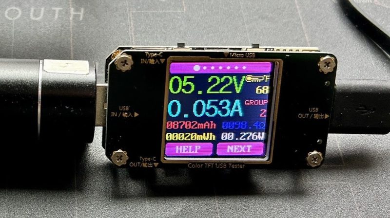
[PatH] had this very problem recently, when trying to work with Meshtastic running on a RAKwireless WisBlock Base Board. You’re supposed to hook up your own rechargeable LiPo battery, but [PatH] was in a hurry. Instead, a USB battery pack was pressed into service, but it kept shutting down. The simple trick was to just add a 100-ohm resistor across the device’s battery terminals. That took the current draw from just 15 mA up to 53 mA, which was enough to keep portable USB power banks interested in staying switched on.
It’s an easy hack for an oddball problem, and it just might get you out of a bind one day. If you’ve got any nifty tricks like this up your sleeve, don’t hesitate to let us know!


I do not really consider 15mA “low power gear”, and pumping it up to 53mA is just atrocious.
There are plenty of “battery managment PCB’s”, that meant for this task and they are not very expensive. It’s worth having a few lying around.
https://www.youtube.com/watch?v=-SJbdPvgQnE
Also, recently I saw a youtube video about drawing short current pulses out of a power bank. Just enough to prevent the power bank from shutting down, while keeping the average current draw modest. I think that video was also from Andreas Spiess, but I’m not sure. There are probably also others who made a video about the same idea.
It was from Andreas Spiess. https://youtu.be/SgV6_Y_sg4k?si=tsaJpbVTtHExtCx8
And it was based on a Great Scott video. https://youtu.be/ty5JueA1wRc?si=ONC1NCDaPXrDqJZ8 (I think it was this one)
Yes, for a moment I thought this was about Andreas’ board with an ATtiny. To be fair he said he was inspired by Great Scott’s video about the same problem, which he fixed with the obligatory 555.
Scott’s solution was an example of horrible engineering. I really don’t like that guy, as he actually is not that great at electronics.
Andreas did it better, but both made both were trying to solve a problem that doesn’t really need a solution. The proper way to do it is to use battery directly. On can get single 18650 cells and charging modules for them very cheaply – I extracted hundreds of them from old laptop batteries. Those charging modules with battery protection are cheaper than single ATTiny. There is no good reason for using an USB power bank.
I’m working on a low power gadget that will draw on average a few microamps. I calculated that it will operate for over 3 years on single CR2032 cell. It’s an update to older project that used 555, and worked for 12 hours on four button cells…
Agreed 100% !
Did you forget that you’re reading this on hackaday? Of course there are better ways but sometimes the best way is to use what’s on hand
But still it’s a good hack to albeit a bit unnecessary
Like when I’m trying to charge my comatose miband from a power bank
IronOS (Pinecil and TS* soldering iron firmware) has an option to briefly turn on the heater FET every few seconds when idling to appease power banks. It’s not enough to heat the tip appreciably, but enough to keep the lights on.
Sometimes a quick solution that will kinda work okayish is needed = “a hack”…
This could be a schoolbook example of hardware hack – simple and practical but not elegant nor optimal.
Most of us probably wached both Scot and Andreas trying to find quality and proper solution for this problem – but that asumes planing ahead and more time for implementation hence it wouldn’t be a hack…
+1
It’s a *hack* folks. For when the show is starting and nothing else is available.
It would be interesting to see if a sporadic “high” load would also work. And if so, then for how ling no and how often to fool most USB banks.
Or this an already known thing?
Yeah, it’s a known thing that is only a problem with “nice” powerbanks for some reason. Y’know, the annoying ones that won’t turn on unless you press a button.
If you look up the datasheets for the driver IC they’ll specify the minimum current draw and the timeout period. Given their standby current is usually in the nano-amps I’m not sure why they bother.
The simplest I’ve seen was a two transistor oscillator that had a short 100mA load every 45 seconds or something like that. I’ve seen people mention some have the timeout as low as 20 seconds.
Its funny indeed only ‘nice’ ones turn off. The cheapest ones will happily stay on and even allow charging while drawing power. There are some ‘really nice’ powerbanks that habe ‘staying on’ as a feature but they are even more expensive
Might be able to use a high value (farad range) cap to power the wake up circuit to extend the time interval.
Just add more LEDs to your project. Problem solved!
Yes. Had the same issue on a project, tried to get it under a mA on 18650 batteries, while the customer just wanted to power it from a powerbank.
Added blinking LEDs, the current of over 50mA is enough to trigger most Powerbanks to stay on for 5 to 10 seconds, so had something LED in something like 500ms on – 1500ms off. Because using power just for kicks isn’t my forte.
And the project now had a visible “it’s working” vibe, while on battery it just sits there .. most of the time doing nothing.
That’s what I came to post!!
It seems like a small resistor – can it handle the 1/4W power dissipation without getting too hot?
Now, my thought was, could the value of the resistor be varied to adjust the current across it, so the total current would be just enough to keep from tripping out the power bank? The value might even have to be different for different power banks.
Been there as well; nice trick, but at the expense of discharging the power bank faster. There must be more elegant solutions for this problem out there.
Or, you know, check the manual on your USB battery pack. The Anker I use goes into low-power trickle mode when I double-tap the button.
Cheap powerbanks work fine without have a stupid button where you have to read the stupid manual to see what it does.
Powerback standby current is tiny. Why people keep implentmenting this dumb crap is beyond me.
This is the answer I expected to see when reading this article. Spot on from the engineers at Anker as this is a very useful feature, though probably not for the average consumer.
“More power” isn’t really a hack…
Not all power banks are created equal! I just bought a few random (cheap!) usb power banks and found one that does not shut down.
Brand?
And while I’m thinking about it, I’ll ask to see if someone can offer a name-brand (so I can find it in the store or online) battery bank that does all the following:
o Stays on even with with low power drain on its output;
o Delivers power on its output when it’s being charged;
o Continues to output (without interruption or glitches) when its input loses power;
o Powers back up on its own after being discharged during a long power-loss event;
o Supports USB-A (at the least) and USB-C.
In other words, a USB-output UPS. There’s a nice add-on board for the Raspberry Pi Zero that does most/all of that, but I’m looking for something more universal for USB devices.
Yep the cheapest ones will just give you power, most likely you can even charge them while drawing power as well!
I’ll have to go back and re-check my various no-name (and some known-branded) power packs to see if they output while charging. Maybe I mis-tested, or I’m just unlucky, but the last time I tried them out none of mine worked that way.
Some clues here: https://hackaday.com/2022/01/31/open-hardware-5v-ups-improves-on-cheap-powerbank-design/
None of this should be an issue on a compliant USB-C bank, from what I hear they are supposed to stay on until the load tells them to stop, even though some might not actually follow the rules.
What is the cutoff for the lode?
I work on a lot of lower power IoT devices (power usage in uW), and I like the power banks from voltaic systems. They’re just a normal battery bank, but they don’t shut off. Hugely nice for testing.
Any word on tricking the current read loop to accept 15mA as a valid draw? Adjust the sensitivity on it?
100mA isn’t too egregious for a quick hack.
A lot of people’s comments have me wondering if they have forgotten both the meaning and purpose of the word ‘hack’. If there wasn’t an option that takes more time and effort but is demonstrably more ‘correct’ then it wouldn’t be a hack.
Sometimes well enough and right now is better than waiting for the amazon truck to bring your correct parts.
Or put another way.. this IS the correct way to make it work right now. If it’s going into permanent battery powered service then the correct battery and charge controller may be added later. Otherwise… that would be a waste of time.
10 Yeats ago: https://hackaday.com/2013/11/08/tricking-a-usb-power-supply/