We’ve all been there. You’ve cooked up some little microcontroller project, but you need to unhook it from your dev PC and go mobile. There’s just one problem — you haven’t worked up a battery solution yet. “No problem!” you exclaim. “I’ll just use a USB battery pack!” But the current draw is too low, and the pack won’t stay on. “Blast!” you exclaim, because you’ve been watching too much Family Guy or something.
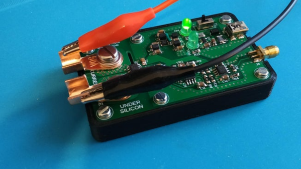
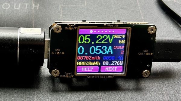
[PatH] had this very problem recently, when trying to work with Meshtastic running on a RAKwireless WisBlock Base Board. You’re supposed to hook up your own rechargeable LiPo battery, but [PatH] was in a hurry. Instead, a USB battery pack was pressed into service, but it kept shutting down. The simple trick was to just add a 100-ohm resistor across the device’s battery terminals. That took the current draw from just 15 mA up to 53 mA, which was enough to keep portable USB power banks interested in staying switched on.
It’s an easy hack for an oddball problem, and it just might get you out of a bind one day. If you’ve got any nifty tricks like this up your sleeve, don’t hesitate to let us know!