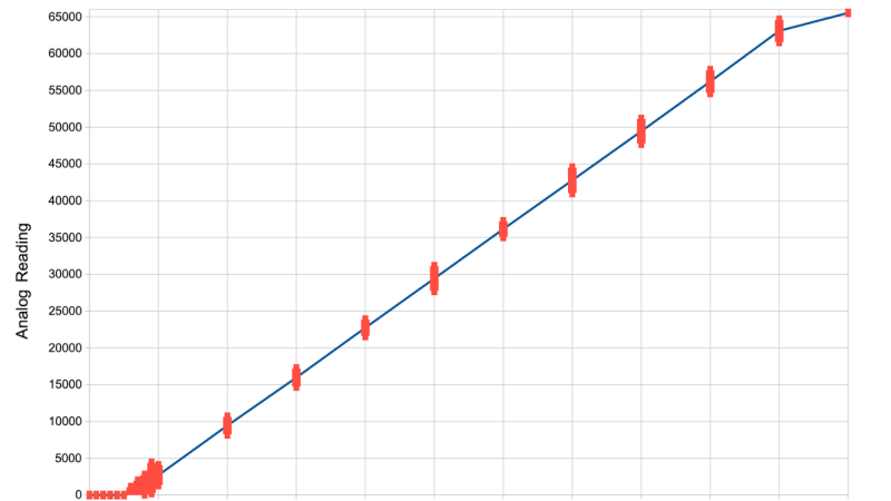
[Simon Monk] got frustrated with bad ADC performance when tinkering with an ESP32 board, and decided to put three of the nowadays-iconic boards to the test – a classic ESP32 devboard, a Pi Pico with an RP2040, and an Arduino Uno R3 with an ATmega328P. To do that, he took a bench PSU, added a filter circuit to it, went through the entire ADC range for each board, took a large number of samples at different points and plotted the results. The plots show us both linearity and precision, as well as ADC dead zones, and the results are quite surprising.
The ESP32 doesn’t only have the most limited ADC with maximum 1V input, it also produces the worst results out of all three, with large error bars and sizeable dead zones at both ends. The Pi Pico, despite being colloquially known for its subpar ADC, produces better results than the ESP32. However, both of them are dwarfed by the ATMega328P’s performance. If you need a dedicated ADC, it might just be a good idea to put an ATMega328P on your board.
The example code is provided, and we are wondering whether there are methodology errors. For instance, the ATMega328P code is written in Arduino-supplied C++, but ESP32 and RP2040 in particular used MicroPython, which does more than just running the code, and MicroPython for ESP32 in particular creates a WiFi access point – something known to induce noise into ADC readings. Nevertheless, this is a fun comparison, and we like when hackers do microcontroller standoffs like that – for instance, check out this review from 2017 which pits a dozen microcontrollers of the time against each other!


It’s sad Espessif does so poorly with their ADCs… But their micros are so damn cheap and supported by so many great projects (Think Home Assistant) that I tend to use those over Atmegas anyway. At least where energy consumption isn’t restricted to batteries. When I really need an ADC I’ll add an external one…
I still love my Atmegas for many other purposes though ☺️
https://lcamtuf.substack.com/p/dacs-and-adcs-or-there-and-back-again there are many ways to build an ADC
Just use a 555 as an ADC. Look for any trivial circuit that turns a 555 into a VCO, and just count the pulses.
https://www.learningaboutelectronics.com/Articles/Voltage-controlled-oscillator-VCO-circuit-with-a-555-timer.php
I’m not sure about the 555 linearity when used as a VCO, but a LM331 would certainly work. Beware of fakes however; buy it only from reputable sellers, or the chances of getting a counterfeit are close to 100%.
If you need a 12-bit 80 MSPS ADC with an ARM M4 and two M0 co-processors a LPC4370 might be option, cheaper than a dedicated MCU/MPU and dedicated ADC. There are two potential problems with it for some projects it is a BGA part and if you want to transfer the samples off the MCU you will probably be limited to 40 MSPS due to USB 2.0 High-speed. Well maybe 48 MSPS with bit packing
Sorry I meant 20 MSPS (no bit packing) and 24 MSPS (bit packing) although you could probably do 40 MSPS if you only wanted 8-bit samples (dropping a nibble from every 12-bit sample).
This touches on the 2nd ADC property: sample rate.
Slow changes are easier to sample. RF, or even ultrasonics, will need a significantly higher sample rate.
With the CPU running at 204 MHz you have 2.5 cycles to process a sample at 80 MSPS. You need at least 1 cycle to load the sample into a register. So you basically can’t do any sustained processing at this speed. Basically your only options are sending the data straight to an other peripheral via DMA (I’m not sure if this controller supports peripheral to peripheral DMA) or sampling short bursts of data an processing them later. For me it is already quite challenging to do some processing on the output of the 1MSPS ADC of the STM32G474 without interruptions.
I would be interested to hear some real life examples where such an ADC is useful.
Without a very close to identical code base, this is comparing apples and oranges…
get sample from adc, print sample result.
with a calibrated voltage source, there is not much that can go wrong. Set the ADC registers get the same, optionally average a few samples, etc. There is no “magic” going on here.
No sample time conversion, averaging, software tricks, etc.
It would have to be EXCEPTIONALLY BAD code under the hood to call this apples to oranges. As “bill gates” says, it’s just reading the ADC and printing it. The minimum viable task under each code base should each only do the bare minimum to get a slow reading out in a dependable and predictable way. These libs are essentially no different than the manufacturer recommended ADC demo code (which should be “putting their best foot forward”, i.e. “it just WORKS.”) We have all had enough recurring evidence to support that the ESP ADC is terrible. That’s not conjecture. Its fact. With or without the wifi/bluetooth radios in operation. Its also not great for highish speed, reliable timing of IO. Still a great chip for a lot of things. Just add an ADC or secondary micro for measurement work.
when in doubt read the datasheet. people are spoiled with the arduino way of doing things where you just find the right library. it turns out many of the peripherals are highly configurable and you can get so much better control over them if you talk to the registers directly. i don’t like seeing overcomplicated workarounds to problems caused by libraries that can be eliminated by cutting out the middle man entirely.
It’s highly relevant to casual users.
It’s a bit like comparing fuel economy from one vehicle to the next, but then pointing out that the two vehicles have different aerodynamics so you should drive one at a different speed to get the best economy, etc.
For people who just want to write some very basic code and get a result, this is very useful information.
It would be far more interesting if someone very experienced with the ESP32 did the testing. The author here raises a good point regarding WiFi, but there’s a lot more…
Most importantly, each ESP32 comes with its individual calibrated reference voltage in efuses. Simon makes no use of this.
ESP-IDF includes calibration curves to account for the non-linearity. Simon makes no use of these. Espressif also recommends multisampling.
If you really want to get technical, digging into ESP32’s ADCs will reveal many registers dedicated to tweaking parameters of the conversion, such as timings. Simon makes no use of these.
If the point here was to demonstrate that a very naive ADC conversion on ESP32 can be inaccurate, then mission accomplished I guess. But I hope nobody is actually misled by this into believing that the ESP32 ADC cannot be accurate enough to be adequate for the vast majority of typical ADC tasks on a MCU. It’s fine.
The more recent ATtiny 2-series and the newer AVR DD etc even have a 12 bit ADC. With oversampling you can get up to 15 bits.
MircoPython on the ESP32 only turns on the WiFi peripheral if you turn it on. Don’t know why it would be necessary to do that.
ADC2 is multiplexed with the WiFi peripheral for power detection somehow.
Simon Monk didn’t do his homework for the ESP32. From his code he never ran the calibration first.
That WOULD be comparing apples to oranges. If the purpose of the test is to say “what you get, out of the box..” then allowing one particular device to go through calibrations is an unfair advantage.
The point is, out of the box, most other micros have far superior ADCs, and can mostly be relied on to be accurate from the start.
Also, just in general, needing to either go through external, manual calibration steps (like precisely measuring an reference output), or even needing to go through software calibration steps during boot up (which may, for example, require disconnecting the analog input momentarily) are not really production friendly requirements.
No runtime calibration is required, the individual chip offset is burned into efuses at the factory and the lookup table is provided in ESP-IDF.
This is apples to oranges because the value from the ADC is effectively an arbitrary value that *must* be converted into the respective voltage. Treating the raw value from the ADC as the voltage on the pin is naive and misguided. The relationship is not even linear.
It’s 2 extra lines of code to convert the raw value to a voltage value. ESP32 ADC is fine for 99% of things anyone with an ESP32 needs an ADC for. Unfortunately, articles like this mislead people into thinking otherwise.
>far superior ADCs
An old slow ADC with little bandwidth like in the AVR chip can have better linearity and noise “out of the box” than the faster actually superior ADC on default settings without calibration.
If you set the sampling parameters to be equal, I bet you the more modern ADC will perform better.
There should be a configurable attenuator on ESP32 to bring up to 2.5V scale signal down to the 1V ADC scale.
https://docs.espressif.com/projects/esp-idf/en/v4.4/esp32/api-reference/peripherals/adc.html
As for WiFi, it pulses 240 mA. Single ended ADC probably won’t tolerate it that well…
Why run the 1V adc to 1.1V then claim it has a dead spot at the end but then not run the 3.3V adc to 3.6V and the 5V adc to 5.5V? Pretty sure they will all have the same dead spot.
It also looks like all the adcs have the same dead spot below 0.05V this is only obscured by different scaling on the graphs.
“Stable on a voltmeter” – Voltage meters average the signal so stability on a voltmeter means nothing. It would be more interesting to see what his power supply’s output voltage looks like on an oscilloscope. If you want a more stable input you should use batteries and a resistive divider. It won’t be perfect but it likely won’t be oscillating either.
Another issue is that his tests are running at DC and give no indication of how performance will be at higher frequencies. The Pico can provide 500ksps throughput using DMA. The ATMEGA around 56ksps. That’s a pretty big difference for those that need it.
Finally, ATMEGA is certainly a capable microcontroller, but its specifications are pretty limited these days. The number of GPIO pins, low clock speed, comparatively low memory, no wifi or bluetooth, and on and on would lead me to only choose it if I was taking samples at longer intervals and in scenarios where the actual precision really wasn’t that important. It just isn’t the right platform for trying to do any serious digital signal processing.
I would even consider using an ESP32 with an external ADC before choosing the ATMEGA for digital signal processing projects. Again, the ATMEGA is a great little microcontroller for certain things. Just not for digital signal processing of any magnitude.
About a decade ago I used SAMD09 with an esp8266 for exactly this reason. A cheap 12 bit ADC with processing, so digital filtering is available before the wifi chip, but also it provides an intelligent IO expansion. The 2 wire serial comms saves on pins, and if you can add some critical function on the ADC chip, you have a basic form of copy protection. You can store parameters, like the SSID or password on the SAMD’s internal eeprom, preventing exposure of the sites SSID and password in the event of the unit leaving the installation site. I have also found it useful to have an applications processor (the esp8266 in this case) and a HAL processor (the SAMD09 in this case), this greatly simplified the replacing of the application processor as all application specific hardware, tight interrupts etc are abstracted away. Additionally, the applications processor can be substituted by a PC with a serial port. This speed development, or debugging.
Finally, it is important to remember to add small capacitor near the input pin of a micro’s ADC. Although the ADC pin may have a high input resistance, the sample and hold capacitor’s charging energy within the micro can distort a high impedance signal, especially at high speed. A small input pin capacitor to ground can swamp the distorting influence of a couple of picofarads of sample and hold, providing more consistent, more accurate results.
Silicon errata discusses RP2040, ESP32 ADC flaws. Always refer to the doc before using a MCU. It’s unfortunate these two MCU’s have poor analog performance, lucky to get 9 bits worth after calibration and all that hassle.
We always want more, its perfectly natural. However in both cases they are really really cheap and capable chips, with functional ADC features as only part of a pretty large repertoire, so I’d not complain at the ADC performance being less than perfect… We don’t want to spend $40 or even $4000 for the single chip that ‘can do everything perfectly’ – if you really really need great ADC you get something that specialises that way etc…
“If you need a dedicated ADC, it might just be a good idea to put an ATMega328P on your board.”
Or, you know, use a proper dedicated ADC IC for a dedicated ADC…
Interesting article.
Despite the esp32 variance in the readings taken and the non linear relationship between ADC and the actual voltage measured, these problems are easily negotiated by oversampling and applying an appropriate polynomial equation that best fits the data.
For example, using the i282 module I can measure current shunts and be accurate to within 0.2A of a 75A range. So this is accurate to 0.3%. esp32’s are awesome, end of story.
The ESP32’s 0V to 1V ADC is a known stinker. The RP2040’s ADC has big known performance problems as well. See here:
* ADC has very high DNL spikes and low-noise mode has more noise.
https://github.com/raspberrypi/pico-feedback/issues/91
* Characterizing the Raspberry Pi Pico ADC
https://pico-adc.markomo.me/