A graph from the article, showing dead zones and error bars for the ESP32 ADC

RP2040, ESP32, And An Atmega Have An ADC-Off

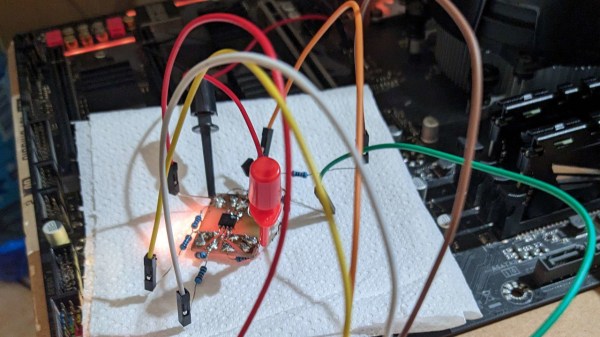
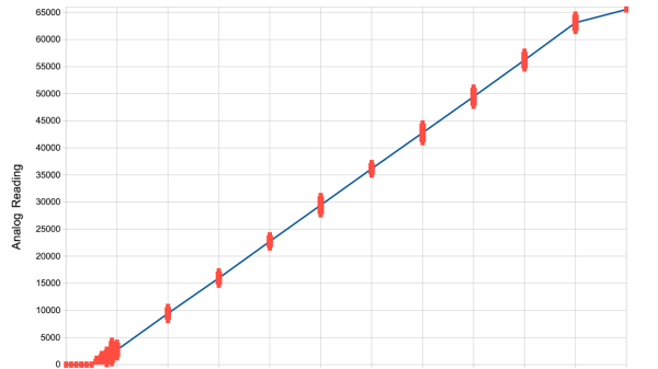
[Simon Monk] got frustrated with bad ADC performance when tinkering with an ESP32 board, and decided to put three of the nowadays-iconic boards to the test – a classic ESP32 devboard, a Pi Pico with an RP2040, and an Arduino Uno R3 with an ATmega328P. To do that, he took a bench PSU, added a filter circuit to it, went through the entire ADC range for each board, took a large number of samples at different points and plotted the results. The plots show us both linearity and precision, as well as ADC dead zones, and the results are quite surprising.

The ESP32 doesn’t only have the most limited ADC with maximum 1V input, it also produces the worst results out of all three, with large error bars and sizeable dead zones at both ends. The Pi Pico, despite being colloquially known for its subpar ADC, produces better results than the ESP32. However, both of them are dwarfed by the ATMega328P’s performance. If you need a dedicated ADC, it might just be a good idea to put an ATMega328P on your board.

The example code is provided, and we are wondering whether there are methodology errors. For instance, the ATMega328P code is written in Arduino-supplied C++, but ESP32 and RP2040 in particular used MicroPython, which does more than just running the code, and MicroPython for ESP32 in particular creates a WiFi access point – something known to induce noise into ADC readings. Nevertheless, this is a fun comparison, and we like when hackers do microcontroller standoffs like that – for instance, check out this review from 2017 which pits a dozen microcontrollers of the time against each other!

Raspinamp: It Really Replicates Questionable Activities Involving Llamas

In the late 90s as MP3s and various file sharing platforms became more common, most of us were looking for better players than the default media players that came with our operating systems, if they were included at all. To avoid tragedies like Windows Media Center, plenty of us switched to Winamp instead, a much more customizable piece of software that helped pave the way for the digital music revolution of that era. Although there are new, official versions of Winamp currently available, nothing really tops the nostalgia of the original few releases of the software which this project faithfully replicates in handheld form.

The handheld music player uses a standard Raspberry Pi (in this case, a 3B) and a 3.5″ TFT touchscreen display, all enclosed in a clear plastic case. With all of the Pi configuration out of the way, including getting the touchscreen working properly, the software can be set up. It uses QMMP as a media player with a Winamp skin since QMMP works well on Linux systems with limited resources. After getting it installed there’s still some configuration to do to get the Pi to start it at boot and also to fit the player perfectly into the confines of the screen without any of the desktop showing around the edges.

Although it doesn’t use the original Winamp software directly, as that would involve a number of compatibility layers and/or legacy hardware at this point, we still think it’s a faithful recreation of how the original looked and felt on our Windows 98 machines. With a battery and a sizable SD card, this could have been the portable MP3 player many of us never knew we wanted until the iPod came out in the early 00s, and would certainly still work today for those of us not chained to a streaming service. A Raspberry Pi is not the only platform that can replicate the Winamp experience, though. This player does a similar job with the PyPortal instead.

Continue reading “Raspinamp: It Really Replicates Questionable Activities Involving Llamas”

Probes connected from a Pi Pico board to the SPI flash chip, with other end of the probes connected tot the level shifter circuit resistors

Motherboard Revived With Simplest 1.8V SPI Shifter Ever

If you have ever had to fix a modern desktop motherboard, you might have noticed that the BIOS (UEFI) SPI flash is 1.8V – which means you can no longer use a Raspberry Pi or a CH341 adapter directly, and you’d need to use a 1.8V level shifter of some sort. Now, some of us can wait for a 1.8V level shifter adapter from an online store of your choosing, but [treble] got a “BIOS flash failed” motherboard from Facebook Marketplace, and decided to make it work immediately.

She tells us a story about reviving the motherboard, and there’s one thing she shows that is interesting in particular – a very simple way to level shift 3.3V signals from a serprog-flashed Pi Pico down to the 1.8V that the flash chip required, something you are guaranteed to be able to build out of the parts in your parts bin, only requiring nine resistors and an NPN transistor. If you ever need to reflash BIOS on a modern motherboard, take note. As for 1.8V rail, she ended up tapping the 1.8V power pin of the SPI chip the motherboard itself to power the chip while programming it.

In the end, after swapping the two BIOS chips places and fixing a broken trace mishap, the motherboard booted, and works wonderfully to this day, a much-needed upgrade to [treble]’s toolkit that allows her to do RISC-V cross-compiling with ease nowadays. This is not the first time we see people reflash modern boards with 1.8V chips – if you want to learn more, check out this incredibly detailed writeup! Need to do some further debugging? Use your Pico as a POST card!

A multifactor authentication device showing TOTP codes

An ESP32 MultiFactor TOTP Generator

MFA, or multifactor authentication, is a standard security feature these days. However, it can be a drag to constantly reach into one’s pocket, scroll to Google Authenticator (other MFA applications are available!), and find the correct TOTP code to log in to a site for a short while. [Allan Oricil] felt this pain point, so they took the problem by the horns and created a desktop MFA TOTP generator to make life just that little bit easier.

TOTP, which stands for Time-based One-Time Password, is a security measure that uses a device or application to provide unique codes that expire after a short time. Two-factor authentication requires a physical item (something you have), such as a key or swipe card, and knowledge of a fact (something you know), like a password, rather than relying on a single factor. This approach ensures a higher level of security. [Allan]’s project is a physical thing one would use with a password or key file.

Continue reading “An ESP32 MultiFactor TOTP Generator”

Micro Jeep Model Kit Is Both Business Card And Portfolio

When finding work in product design and prototyping, two things are important to have at hand: a business card, and a sample of one’s work. If one can combine those, even better. Make it unique and eye-catching, and you’re really onto something. That seems to  have been the idea behind [agepbiz]’s 1:64 scale micro Jeep model kit that serves as an  “overcomplicated” business card.

Complete with box and labels in a shrink-wrapped package.

At its heart, the kit is a little print-in-place model kit that looks a lot like larger injection-molded model kits. Completing it is a custom-made box with custom labels, and it’s even shrink-wrapped. The whole thing fits easily in the palm of a hand.

There’s a lot of different tools effectively used to make the whole thing. The model card itself is 3D printed in multiple filament colors, and the box is constructed from carefully glued cardstock. The labels are custom printed, and a craft cutter (which has multiple uses for a hobbyist) takes care of all the precise cutting. It’s an awfully slick presentation, and the contents do not disappoint.

Get a closer look in the video, embedded just below. And if you like what you see, you’re in luck because we’ve seen [agepbiz]’s work before in this mini jet fighter, complete with blister pack.

Continue reading “Micro Jeep Model Kit Is Both Business Card And Portfolio”

Ethernet For Hackers: Transformers, MACs And PHYs

We’ve talked about Ethernet basics, and we’ve talked about equipment you will find with Ethernet. However, that’s obviously not all – you also need to know how to add Ethernet to your board and to your microcontroller. Such low-level details are harder to learn casually than the things we talked about previously, but today, we’re going to pick up the slack.

You might also have some very fair questions. What are the black blocks near Ethernet sockets that you generally will see on boards, and why do they look like nothing else you see on circuit boards ever? Why do some boards, like the Raspberry Pi, lack them altogether? What kind of chip do you need if you want to add Ethernet support to a microcontroller, and what might you need if your microcontroller claims to support Ethernet? Let’s talk.

Transformers Make The Data World Turn

One of the Ethernet’s many features is that it’s resilient, and easy to throw around. It’s also galvanically isolated, which means  you don’t need a ground connection for a link either – not until you want a shield due to imposed interference, at which point, it might be that you’re pulling cable inside industrial machinery. There are a few tricks to Ethernet, and one such fundamental Ethernet trick is transformers, known as “magnetics” in Ethernet context.

Each pair has to be put through a transformer for the Ethernet port to work properly, as a rule. That’s the black epoxy-covered block you will inevitably see near an Ethernet port in your device. There are two places on the board as far as Ethernet goes – before the transformer, and after the transformer, and they’re treated differently. After the transformer, Ethernet is significantly more resilient to things like ground potential differences, which is how you can wire up two random computers with Ethernet and not even think about things like common mode bias or ground loops, things we must account for in audio, or digital interfaces that haven’t yet gone optical somehow.

Continue reading “Ethernet For Hackers: Transformers, MACs And PHYs”

CT Scan Reveals Secrets Of Heinz’s New Ketchup Cap

Ketchup bottles are a solved technology, right? Wrong! As it turns out, there is still great development being done in this space. Industrial imaging company Lumafield reveals to us the secrets of Heinz’s new ketchup bottle cap, reportedly the result of a seven-figure investment and eight long years of toil.

Lumafield put the cap in a CT scanner to generate three-dimensional cutaway images of the cap’s internal structure.  The trick of the new cap is in how it compares to the old design. The previous solution used multiple different plastics: likely polypropylene for the cap itself, along with a small amount of silicone for the flexible nozzle valve. The point of the valve was to regulate the flow of ketchup so the bottle squirts out the red goop in a predictable fashion.

The problem with the old cap is that the use of two materials both makes it more expensive to manufacture, and practically impossible to recycle. A solution was needed, and Heinz finally found one.

The new cap, which is fully recyclable, takes advantage of the properties of ketchup itself. As the ketchup is squeezed out of the bottle, it passes through a complicated array of channels before it gets to the nozzle outlet itself. As a sheer-thinning fluid, ketchup gets less viscous the more its under strain. Thus, as it deforms around the complex channels, it becomes less viscous and more likely to flow out at a predictable rate, rather than in thick gloopy spurts.

It’s amazing to think how much work goes into a simple ketchup cap, and yet, millions of dollars are on the line in projects like these. This isn’t the first time Lumafield used their tech to peel back the layers on a piece of common tech — last year we covered their investigation into what’s inside various AirPod knockoffs.